
Deciphering the Language of Air: Understanding the GM 1 Bar MAP Sensor Voltage Chart
Related Articles: Deciphering the Language of Air: Understanding the GM 1 Bar MAP Sensor Voltage Chart
Introduction
With enthusiasm, let’s navigate through the intriguing topic related to Deciphering the Language of Air: Understanding the GM 1 Bar MAP Sensor Voltage Chart. Let’s weave interesting information and offer fresh perspectives to the readers.
Table of Content
Deciphering the Language of Air: Understanding the GM 1 Bar MAP Sensor Voltage Chart
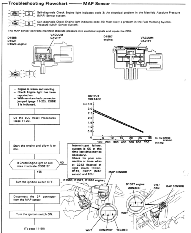
The intricate workings of an internal combustion engine rely on a delicate dance of air and fuel. To ensure optimal combustion, the engine needs to know the precise amount of air being drawn into the cylinders. This is where the Manifold Absolute Pressure (MAP) sensor steps in, acting as a vital component in the engine’s control system.
The GM 1 Bar MAP sensor, commonly found in various General Motors vehicles, is a crucial piece of this puzzle. It translates the pressure within the intake manifold into an electrical signal, which is interpreted by the engine control unit (ECU) to determine the appropriate fuel injection timing and duration.
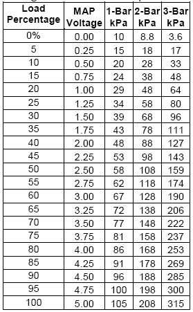
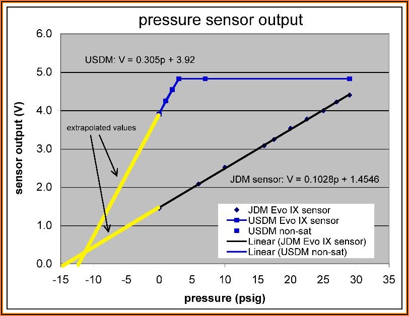
The GM 1 Bar MAP sensor voltage chart is a graphical representation of this relationship, illustrating the correlation between the pressure measured by the sensor and the corresponding voltage output. Understanding this chart is essential for diagnosing engine performance issues and ensuring optimal engine operation.
Delving Deeper: The Mechanics of the MAP Sensor
The MAP sensor is a simple yet ingenious device. It comprises a diaphragm that responds to changes in pressure within the intake manifold. This diaphragm is connected to a variable resistor, which alters its electrical resistance based on the pressure applied.
When the engine is at idle, the pressure in the intake manifold is relatively low, resulting in a low resistance and a low voltage output from the MAP sensor. As the engine revs up and more air is drawn into the cylinders, the pressure increases, leading to higher resistance and a correspondingly higher voltage output.
The Language of the Chart: Interpreting the Data
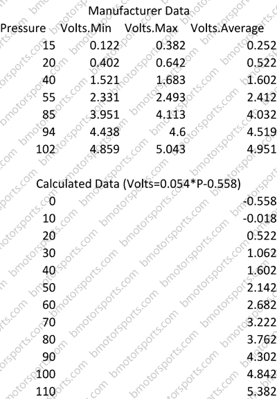
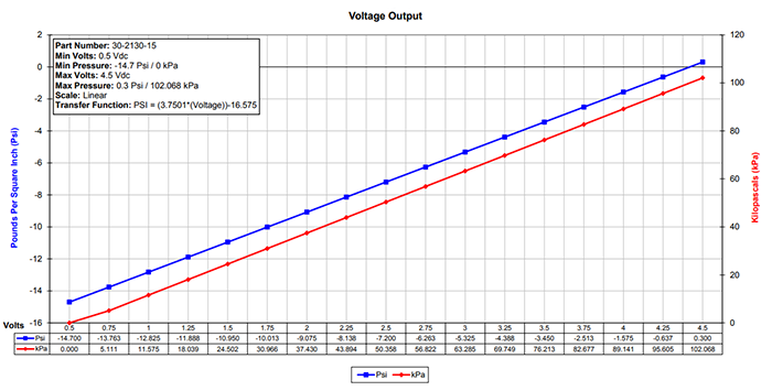
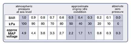
The GM 1 Bar MAP sensor voltage chart typically displays pressure on the X-axis and voltage on the Y-axis. The chart is usually linear, indicating a direct relationship between pressure and voltage.
For instance, a 1 Bar MAP sensor will typically output a voltage of 0.5 volts at 0 PSI (vacuum) and increase linearly to 4.5 volts at 14.7 PSI (atmospheric pressure). This information allows technicians to analyze the sensor’s output in relation to the expected pressure readings under various engine conditions.
The Significance of the Chart: Diagnosing Engine Issues
The GM 1 Bar MAP sensor voltage chart plays a crucial role in diagnosing engine performance problems. By comparing the actual voltage output of the sensor to the expected values on the chart, technicians can identify potential issues such as:
- Sensor malfunction: If the sensor is not producing the correct voltage output for a given pressure reading, it may be faulty and needs replacement.
- Vacuum leaks: A vacuum leak in the intake manifold will cause a lower than expected pressure reading, resulting in a lower voltage output from the sensor.
- Boost issues: In turbocharged engines, a boost leak or malfunctioning boost controller can lead to inaccurate pressure readings and incorrect voltage output.
- ECU problems: A faulty ECU may not be able to interpret the sensor’s output correctly, leading to engine performance issues.
Beyond Diagnosis: Leveraging the Chart for Optimization
The GM 1 Bar MAP sensor voltage chart is not limited to diagnosing problems. It can also be used to optimize engine performance by:
- Fine-tuning fuel maps: The chart provides data that can be used to adjust fuel injection timing and duration for optimal combustion under various operating conditions.
- Calibrating boost controllers: In turbocharged engines, the chart can help calibrate boost controllers to ensure the desired boost pressure is maintained.
- Analyzing engine performance: The chart provides a valuable tool for understanding engine behavior under different loads and speeds, facilitating performance tuning and modifications.
FAQs: Addressing Common Queries
1. What is the difference between a 1 Bar and a 2 Bar MAP sensor?
The difference lies in the maximum pressure range they can measure. A 1 Bar sensor can measure up to 14.7 PSI (atmospheric pressure), while a 2 Bar sensor can measure up to 29.4 PSI, making it suitable for turbocharged engines that generate higher boost pressures.
2. How can I test the MAP sensor using a multimeter?
With the engine off, apply a known vacuum to the sensor inlet. Measure the voltage output using a multimeter and compare it to the values on the chart. If the voltage output deviates significantly, the sensor may be faulty.
3. Can I replace a 1 Bar MAP sensor with a 2 Bar sensor?
In most cases, replacing a 1 Bar sensor with a 2 Bar sensor will not work without reprogramming the ECU. The ECU is calibrated for a specific sensor type and will interpret the signals from a 2 Bar sensor incorrectly.
4. How can I find the correct MAP sensor voltage chart for my vehicle?
The chart can typically be found in the service manual for your specific vehicle model. You can also search online for "GM 1 Bar MAP sensor voltage chart" along with your vehicle’s year, make, and model.
Tips for Using the Chart Effectively
- Use a reliable source for the chart: Ensure you are using a chart that is specific to your vehicle model and sensor type.
- Consider engine operating conditions: The voltage output of the MAP sensor will vary depending on engine speed, load, and temperature.
- Consult a service manual: Refer to your vehicle’s service manual for detailed information on testing and troubleshooting the MAP sensor.
- Seek professional help: If you are unsure about interpreting the chart or diagnosing engine issues, consult a qualified automotive technician.
Conclusion: A Vital Tool for Engine Diagnostics and Optimization
The GM 1 Bar MAP sensor voltage chart is an invaluable tool for understanding and diagnosing engine performance issues. By providing a clear representation of the relationship between pressure and voltage, it enables technicians to identify potential problems and ensure optimal engine operation.
Furthermore, the chart can be used to optimize engine performance by providing data for fine-tuning fuel maps, calibrating boost controllers, and analyzing engine behavior. Understanding the language of the GM 1 Bar MAP sensor voltage chart empowers individuals and professionals alike to ensure the smooth and efficient operation of their vehicles.


Closure
Thus, we hope this article has provided valuable insights into Deciphering the Language of Air: Understanding the GM 1 Bar MAP Sensor Voltage Chart. We thank you for taking the time to read this article. See you in our next article!