
Deciphering the Language of Pressure: Understanding GM MAP Sensor Voltage Ranges by Part Number
Related Articles: Deciphering the Language of Pressure: Understanding GM MAP Sensor Voltage Ranges by Part Number
Introduction
In this auspicious occasion, we are delighted to delve into the intriguing topic related to Deciphering the Language of Pressure: Understanding GM MAP Sensor Voltage Ranges by Part Number. Let’s weave interesting information and offer fresh perspectives to the readers.
Table of Content
Deciphering the Language of Pressure: Understanding GM MAP Sensor Voltage Ranges by Part Number
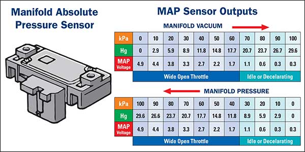
The manifold absolute pressure (MAP) sensor is a crucial component in modern gasoline engines, providing the engine control unit (ECU) with vital information about the pressure within the intake manifold. This data is critical for precise fuel and ignition timing calculations, ultimately impacting engine performance, fuel efficiency, and emissions.
Understanding the specific voltage range of a GM MAP sensor, based on its part number, is essential for diagnosing potential problems and ensuring optimal engine operation. This article delves into the complexities of MAP sensor voltage ranges, providing a comprehensive guide for mechanics, technicians, and automotive enthusiasts alike.
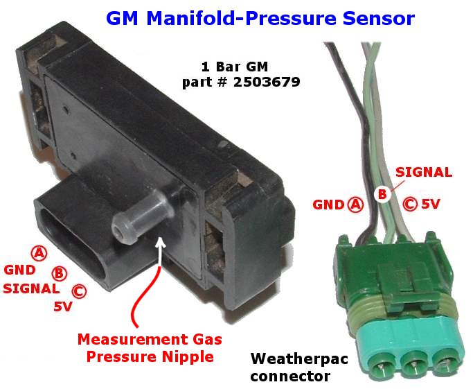
The Role of the MAP Sensor
The MAP sensor, typically a small diaphragm-based device, translates the pressure within the intake manifold into a measurable voltage signal. This signal is then transmitted to the ECU, which uses it to determine the following:
- Engine Load: Higher manifold pressure indicates a heavier load on the engine, requiring more fuel and a more advanced ignition timing.
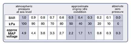
- Air Density: The MAP sensor data allows the ECU to compensate for changes in air density due to altitude or temperature variations.
- Fuel-Air Ratio: By combining MAP sensor data with other inputs like oxygen sensor readings, the ECU precisely adjusts the fuel-air mixture for optimal combustion.
Decoding the Voltage Range: A Vital Parameter
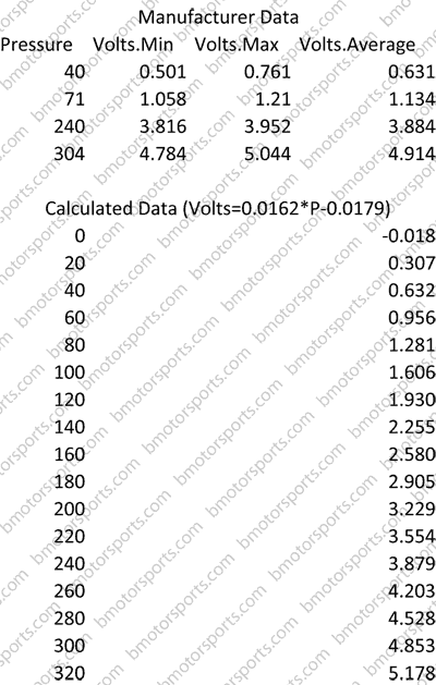
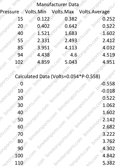
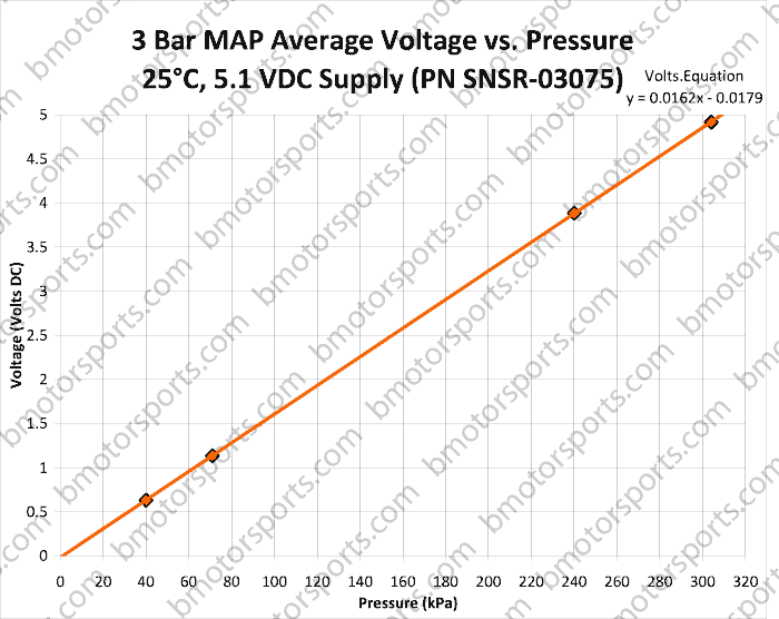
The voltage output of a MAP sensor is not arbitrary. Each sensor has a specific operating range, defined by its minimum and maximum voltage output. This range corresponds to the pressure variations it can detect within the intake manifold.
Understanding the Significance of Part Numbers
GM MAP sensors are often distinguished by their unique part numbers, which provide a wealth of information about the sensor’s specifications, including its voltage range. The part number is a crucial identifier, allowing technicians to quickly determine the correct sensor for a specific vehicle and engine application.
Factors Influencing Voltage Range
Several factors influence the voltage range of a GM MAP sensor, including:
- Sensor Design: Different MAP sensor designs utilize varying technologies and calibration methods, resulting in distinct voltage ranges.
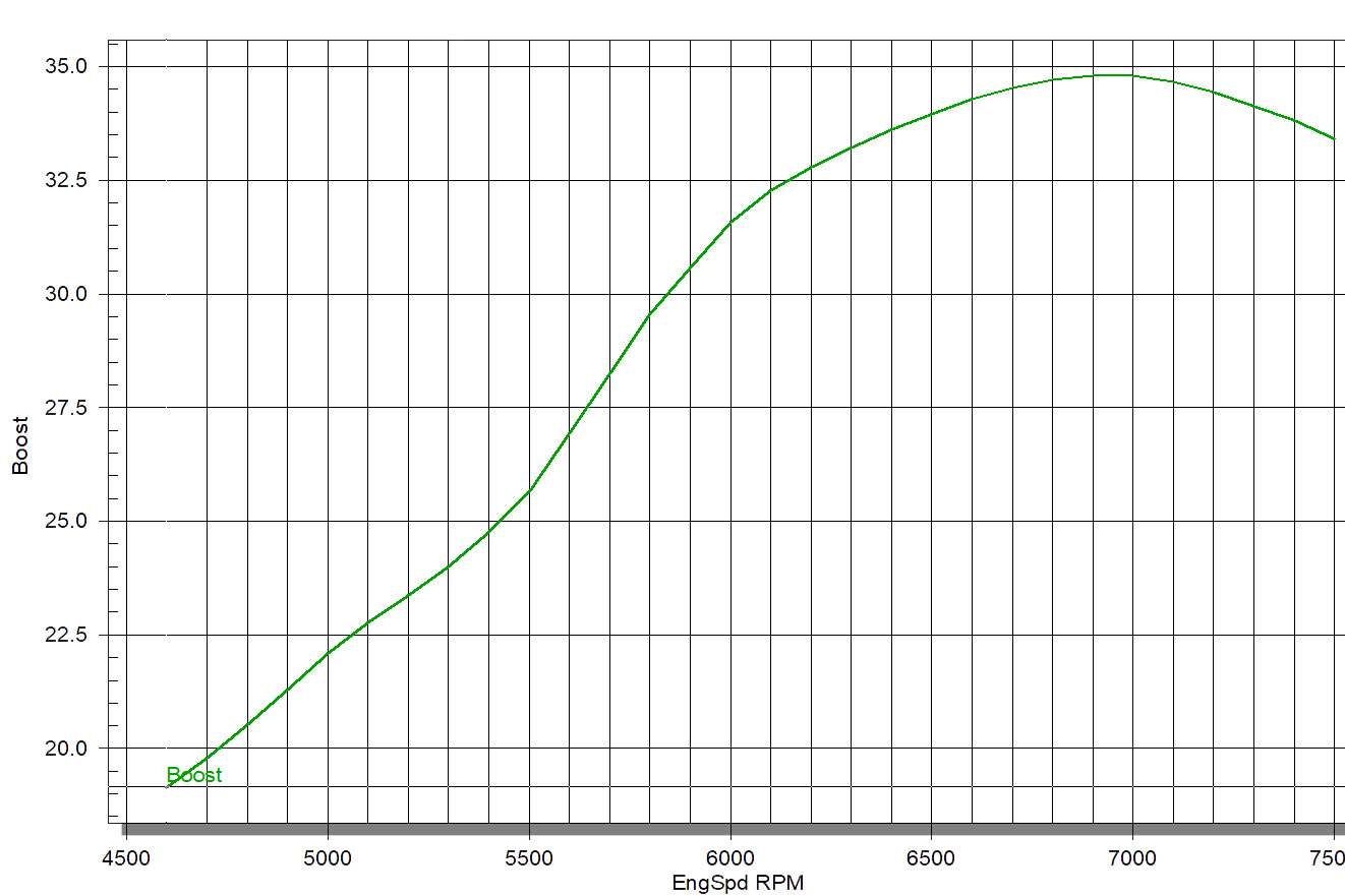
- Engine Application: The specific engine and its operating characteristics, such as turbocharging or naturally aspirated configurations, influence the pressure range the sensor needs to measure.
- Environmental Conditions: Altitude, temperature, and atmospheric pressure can affect the intake manifold pressure, impacting the sensor’s voltage output.
Interpreting Voltage Ranges
The voltage range of a GM MAP sensor is often expressed as a ratio, indicating the relationship between the sensor’s output voltage and the corresponding pressure. For example, a sensor with a voltage range of 0.5-4.5 volts might correspond to an intake manifold pressure range of 0-20 psi.
Diagnostic Applications of Voltage Range Information
Knowing the specific voltage range of a GM MAP sensor is critical for troubleshooting potential issues. If the sensor’s output voltage falls outside its specified range, it could indicate a malfunctioning sensor, a vacuum leak, or a problem with the ECU’s interpretation of the signal.
Using a Digital Multimeter for Diagnosis
A digital multimeter (DMM) is an indispensable tool for diagnosing MAP sensor issues. By connecting the DMM to the sensor’s output signal wire, technicians can measure the actual voltage output and compare it to the expected range.
Typical Voltage Ranges for Common GM MAP Sensors
Here are some examples of common GM MAP sensor part numbers and their corresponding voltage ranges:
| Part Number | Voltage Range (Volts) | Pressure Range (PSI) |
|---|---|---|
| 12577395 | 0.5-4.5 | 0-20 |
| 12583832 | 0.5-4.5 | 0-30 |
| 12590823 | 0.5-4.5 | 0-15 |
| 12607895 | 0.5-4.5 | 0-25 |
Note: These are just examples, and specific voltage ranges may vary depending on the year, make, and model of the vehicle. Always consult the vehicle’s service manual or a reliable online database for accurate information.
FAQs on GM MAP Sensor Voltage Ranges
Q: What is the typical voltage range of a GM MAP sensor?
A: There is no single "typical" voltage range, as it varies based on the specific sensor and its application. However, many GM MAP sensors operate within a range of 0.5-4.5 volts.
Q: Can a faulty MAP sensor cause engine performance issues?
A: Yes, a faulty MAP sensor can significantly impact engine performance. If the sensor is providing inaccurate pressure readings, the ECU will make incorrect fuel and ignition timing adjustments, leading to rough idling, poor acceleration, and reduced fuel efficiency.
Q: How do I test a GM MAP sensor for proper operation?
A: Use a digital multimeter to measure the sensor’s output voltage while applying a known pressure to the sensor. Compare the measured voltage to the expected range for that specific sensor.
Q: How do I determine the correct MAP sensor for my vehicle?
A: Consult your vehicle’s service manual or a reliable online database, such as a parts catalog or repair manual. Enter your vehicle’s year, make, and model to find the compatible MAP sensor part number.
Tips for Troubleshooting GM MAP Sensor Issues
- Inspect the sensor for physical damage: Look for cracks, breaks, or corrosion in the sensor housing or wiring.
- Check for vacuum leaks: Vacuum leaks can cause inaccurate pressure readings and affect the MAP sensor’s output.
- Inspect the wiring connections: Ensure that the sensor’s wiring is securely connected to the ECU and that there are no loose or corroded connections.
- Use a diagnostic scanner: A scanner can read the MAP sensor’s output voltage and identify any potential problems.
Conclusion
Understanding the voltage range of a GM MAP sensor, based on its part number, is crucial for diagnosing potential problems and ensuring optimal engine performance. By utilizing the information provided in this article, mechanics, technicians, and automotive enthusiasts can gain a deeper understanding of this essential engine component and its role in maintaining vehicle performance, fuel efficiency, and emissions control.
Closure
Thus, we hope this article has provided valuable insights into Deciphering the Language of Pressure: Understanding GM MAP Sensor Voltage Ranges by Part Number. We hope you find this article informative and beneficial. See you in our next article!