
Deciphering the Language of the Engine: A Guide to MAP Sensor Pinout
Related Articles: Deciphering the Language of the Engine: A Guide to MAP Sensor Pinout
Introduction
With great pleasure, we will explore the intriguing topic related to Deciphering the Language of the Engine: A Guide to MAP Sensor Pinout. Let’s weave interesting information and offer fresh perspectives to the readers.
Table of Content
Deciphering the Language of the Engine: A Guide to MAP Sensor Pinout

The intricate dance of combustion within an internal combustion engine is orchestrated by a complex symphony of sensors and actuators. Among these crucial components, the Manifold Absolute Pressure (MAP) sensor plays a vital role in ensuring optimal engine performance and fuel efficiency. This sensor, often likened to the engine’s "ear," diligently monitors the pressure within the intake manifold, providing critical data to the engine control unit (ECU). Understanding the MAP sensor’s pinout, the specific arrangement of its electrical connections, is essential for proper diagnosis, repair, and even performance modifications.
The Role of the MAP Sensor
The MAP sensor’s primary function is to measure the absolute pressure within the intake manifold. This pressure, a direct indicator of the amount of air entering the engine, is crucial for determining the appropriate air-fuel mixture for efficient combustion. The sensor’s output, typically a voltage signal, is transmitted to the ECU, which then adjusts the fuel injection and ignition timing accordingly.
Pinout Variations: A Symphony of Connections
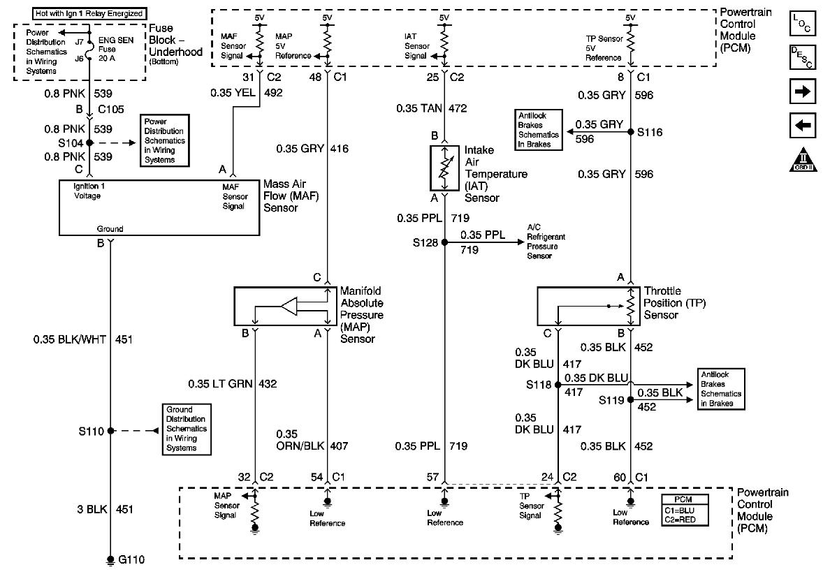
The pinout of a MAP sensor, while generally following a standardized pattern, can vary depending on the specific make and model of the vehicle. Common pinout configurations include:
-
Three-Wire Configuration: This configuration is prevalent in many modern vehicles. The three wires typically correspond to:
- Signal Wire: Transmits the sensor’s output voltage to the ECU.
- Ground Wire: Provides a common reference point for the electrical circuit.
- Reference Voltage Wire: Supplies a stable voltage to the sensor for its operation.
-
Four-Wire Configuration: This configuration is less common but found in certain applications. The fourth wire usually functions as a:
- Heater Wire: Provides a heating element to ensure accurate sensor readings, especially in cold environments.
Decoding the Pinout: A Practical Guide
Understanding the pinout of a specific MAP sensor requires a combination of resources:
- Vehicle Service Manual: The manufacturer’s service manual for the vehicle provides detailed information on the sensor’s pinout, including wire colors and functions.
- Sensor Datasheet: The datasheet for the specific MAP sensor model provides comprehensive information on its pinout, electrical characteristics, and operating parameters.
- Pinout Diagrams: Online resources and automotive repair forums often feature pinout diagrams for various MAP sensors, offering visual representations of the wire connections.
Troubleshooting and Repair: Harnessing the Power of Pinout
The MAP sensor’s pinout plays a crucial role in diagnosing and resolving issues related to engine performance and fuel efficiency. By understanding the wire functions, technicians can effectively:
- Test Continuity: Verify the electrical connections between the sensor and the ECU, ensuring proper signal transmission.
- Measure Voltage: Assess the sensor’s output voltage under different engine conditions, identifying potential malfunctions.
- Identify Wiring Problems: Locate and address faulty wiring connections that could disrupt the sensor’s operation.
- Perform Replacement: Ensure the correct replacement sensor is selected, with a compatible pinout, to maintain proper functionality.
Beyond Diagnosis: Performance Tuning
While the MAP sensor’s primary role is in ensuring efficient engine operation, its pinout can also be utilized for performance tuning. By understanding the sensor’s signal output and its relationship to engine load, enthusiasts can:
- Modify Calibration: Adjust the ECU’s calibration to optimize fuel delivery and ignition timing based on manifold pressure readings.
- Install Boost Controllers: Utilize the MAP sensor’s output to control boost pressure in turbocharged engines, enhancing performance and efficiency.
- Develop Custom Maps: Create custom engine maps that tailor performance to specific driving conditions and desired power levels.
Frequently Asked Questions
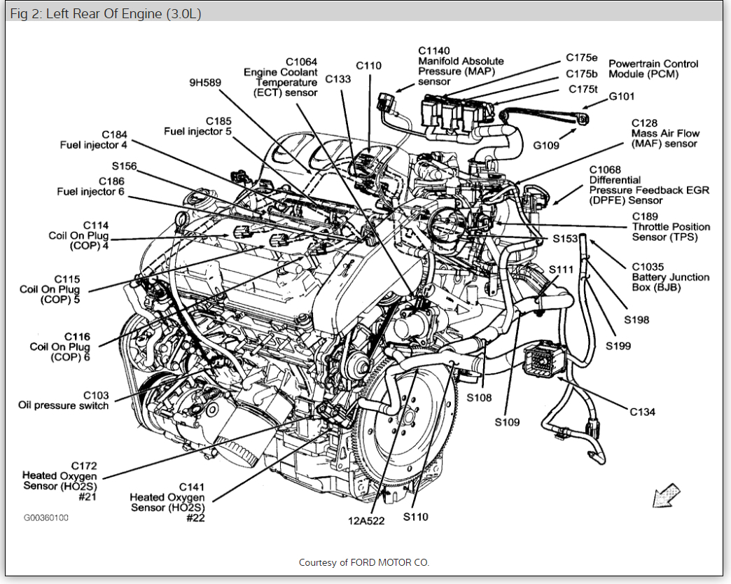
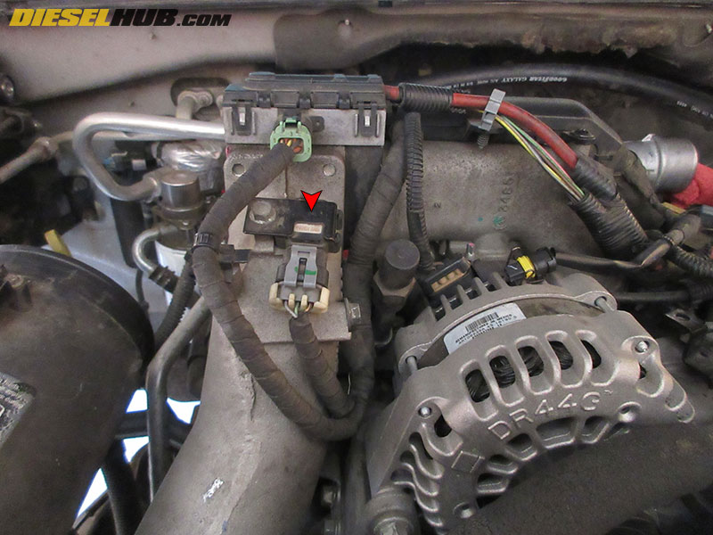
Q: How do I identify the MAP sensor on my vehicle?
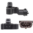
A: The MAP sensor is typically located on the intake manifold, near the throttle body or air intake. It is often a small, cylindrical device with a vacuum hose connected to it.
Q: What are the common symptoms of a faulty MAP sensor?
A: Symptoms of a faulty MAP sensor can include poor fuel economy, engine hesitation or stalling, rough idle, and trouble codes related to engine performance.
Q: Can I test the MAP sensor myself?
A: While a basic continuity test can be performed, a more thorough diagnosis often requires specialized equipment and knowledge. It’s recommended to consult a qualified mechanic for accurate testing and diagnosis.
Q: How do I replace a MAP sensor?
A: Replacing a MAP sensor typically involves disconnecting the electrical connectors, removing the sensor from its mounting location, and installing the new sensor in the same position. Ensure the new sensor is compatible with your vehicle’s pinout configuration.
Tips for Working with MAP Sensor Pinout
- Always consult the vehicle’s service manual or sensor datasheet for accurate pinout information.
- Use a multimeter to test continuity and voltage readings, ensuring proper electrical connections.
- Avoid damaging the sensor’s delicate electrical connections when working with it.
- If you’re unsure about any aspect of MAP sensor pinout, consult a qualified mechanic.
Conclusion
The MAP sensor’s pinout serves as a crucial bridge between the engine’s internal environment and the ECU’s control algorithms. By understanding the sensor’s electrical connections and their functions, individuals can effectively diagnose and repair engine issues, optimize performance, and even unlock new levels of driving enjoyment. Whether you’re a seasoned mechanic or a curious enthusiast, mastering the language of the MAP sensor pinout empowers you to unlock the full potential of your vehicle’s engine.
![[DIAGRAM] Gm Map Sensor Wiring Diagram Free Download - MYDIAGRAM.ONLINE](https://www.justanswer.com/uploads/hdgene/2008-08-25_185855_2008_64_map_sensor.jpg)

Closure
Thus, we hope this article has provided valuable insights into Deciphering the Language of the Engine: A Guide to MAP Sensor Pinout. We thank you for taking the time to read this article. See you in our next article!