
Deciphering the Signals: A Comprehensive Guide to Testing a 4-Wire Manifold Absolute Pressure (MAP) Sensor
Related Articles: Deciphering the Signals: A Comprehensive Guide to Testing a 4-Wire Manifold Absolute Pressure (MAP) Sensor
Introduction
In this auspicious occasion, we are delighted to delve into the intriguing topic related to Deciphering the Signals: A Comprehensive Guide to Testing a 4-Wire Manifold Absolute Pressure (MAP) Sensor. Let’s weave interesting information and offer fresh perspectives to the readers.
Table of Content
Deciphering the Signals: A Comprehensive Guide to Testing a 4-Wire Manifold Absolute Pressure (MAP) Sensor

The manifold absolute pressure (MAP) sensor, a crucial component in modern automotive engine management systems, plays a vital role in determining engine load and optimizing fuel delivery. A four-wire MAP sensor, in particular, transmits a complex signal to the engine control unit (ECU) via four distinct wires, each carrying specific information. Understanding how these wires function and how to test their integrity is essential for ensuring accurate engine performance and fuel efficiency.
The Anatomy of a 4-Wire MAP Sensor
A four-wire MAP sensor typically utilizes the following wiring configurations:
-
Signal Wire: This wire carries the primary signal, which is a voltage output proportional to the absolute pressure within the intake manifold. The ECU interprets this signal to calculate engine load and adjust fuel injection accordingly.
-
Ground Wire: This wire provides a reference ground for the sensor’s internal circuitry, ensuring proper electrical flow.
-
Voltage Supply Wire: This wire delivers a constant voltage from the ECU, powering the sensor’s internal electronics.
-
Reference Wire: This wire provides a reference voltage to the sensor, enabling it to calibrate its output signal accurately.
Understanding the Importance of Testing a 4-Wire MAP Sensor
A faulty MAP sensor can lead to a multitude of engine performance issues, including:
- Poor Fuel Economy: An inaccurate pressure reading can result in over- or under-fueling, leading to wasted fuel and reduced mileage.
- Rough Idle and Stalling: Erratic engine operation, including rough idling and stalling, can be attributed to a faulty MAP sensor misinforming the ECU about engine load.
- Hesitation and Misfires: A malfunctioning MAP sensor can cause hesitation during acceleration and misfires, resulting in a jerky and unpleasant driving experience.
- Check Engine Light (CEL) Illumination: A faulty MAP sensor will often trigger a diagnostic trouble code (DTC) and illuminate the check engine light, signaling a need for inspection and repair.
Testing a 4-Wire MAP Sensor: A Step-by-Step Guide
Testing a four-wire MAP sensor involves verifying the integrity of each wire and confirming the sensor’s ability to generate an accurate pressure reading. Here’s a detailed guide to perform a thorough test:
1. Gather Necessary Equipment:
- Digital Multimeter (DMM): This is essential for measuring voltage, resistance, and continuity.
- Vacuum Pump or Gauge: A vacuum pump or gauge is needed to apply a controlled vacuum to the MAP sensor.
- Schematic Diagram: A schematic diagram of the engine management system will help identify the specific wire connections for the MAP sensor.
- Safety Glasses and Gloves: Protective gear should always be worn when working with automotive electrical systems.
2. Disconnect the MAP Sensor:
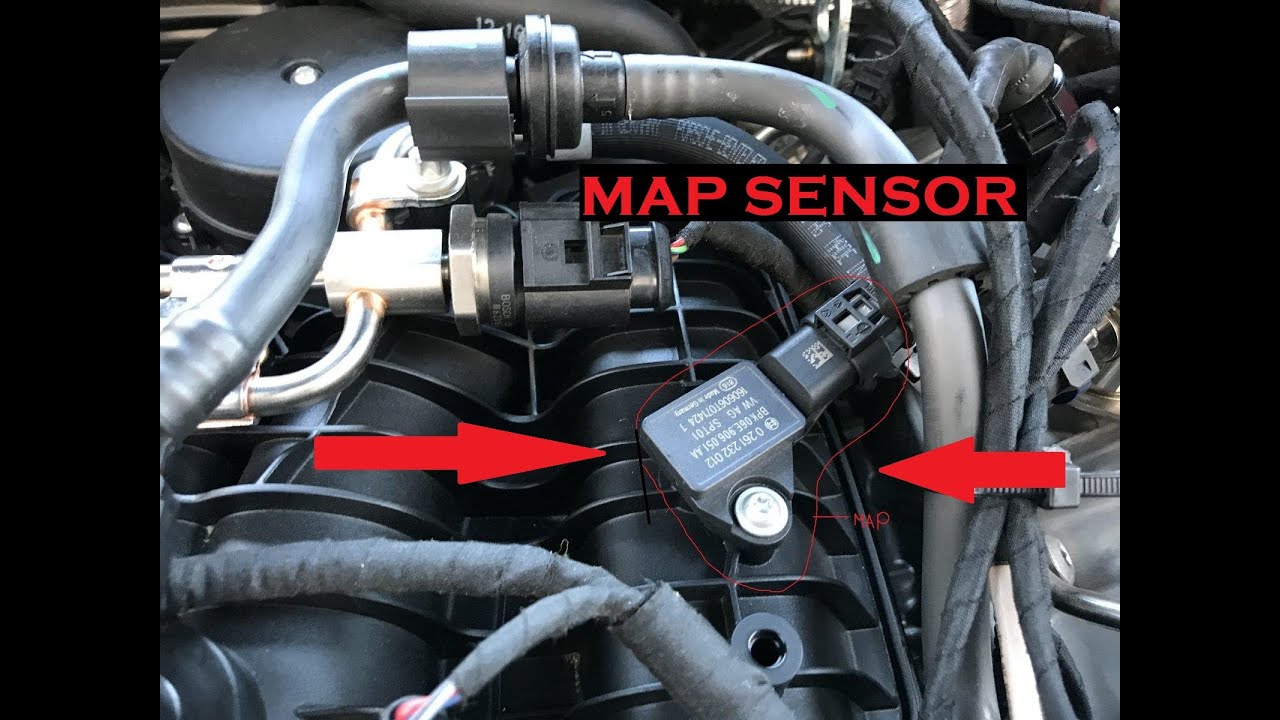
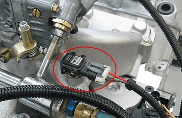
- Locate the MAP sensor, typically mounted on the intake manifold.
- Disconnect the electrical connector from the sensor, ensuring a firm grip to avoid damaging the wires.
3. Visual Inspection:
- Examine the sensor connector for any signs of damage, corrosion, or loose connections.
- Inspect the sensor itself for any visible cracks, leaks, or signs of physical damage.
4. Wire Continuity and Ground Test:
- Continuity Test: Using the DMM in continuity mode, test the continuity of each wire between the sensor connector and the corresponding ECU connector. A continuous beep indicates a good connection.
- Ground Test: With the DMM set to ohms, test the resistance between the ground wire and a known good ground point on the vehicle’s chassis. A low resistance reading (ideally close to zero ohms) confirms a good ground connection.
5. Voltage Supply Test:
- Voltage Check: With the DMM set to DC voltage, measure the voltage between the voltage supply wire and ground. The reading should correspond to the specified voltage for the vehicle’s electrical system (typically 12V).
6. Reference Voltage Test:
- Voltage Check: With the DMM set to DC voltage, measure the voltage between the reference wire and ground. The reading should correspond to the specified reference voltage for the MAP sensor.
7. Signal Wire Test:
- Voltage Check (No Vacuum): With the DMM set to DC voltage, measure the voltage between the signal wire and ground while no vacuum is applied to the sensor. This reading should be close to the reference voltage.
- Voltage Check (Vacuum Applied): Apply a known vacuum to the sensor’s port using the vacuum pump or gauge. This will simulate the pressure changes experienced in the intake manifold during engine operation. Measure the voltage between the signal wire and ground again. The voltage reading should decrease proportionally to the applied vacuum.
8. Interpreting Results:
- Continuity and Ground Tests: If any of the wires fail the continuity or ground tests, it indicates a broken wire or a faulty connection.
- Voltage Supply and Reference Tests: If the voltage readings are significantly different from the specified values, it suggests a problem with the ECU or the wiring harness.
- Signal Wire Test: If the signal wire does not show a significant change in voltage when vacuum is applied, it indicates a faulty MAP sensor.
Troubleshooting and Repair
Once the tests have been completed, any identified problems need to be addressed:
- Broken Wires: Repair or replace any broken wires, ensuring secure connections.
- Loose Connections: Tighten any loose connections to restore electrical continuity.
- Faulty Sensor: Replace the MAP sensor with a new, compatible unit.
- ECU Issues: If the problem lies with the ECU, it may need to be repaired or replaced by a qualified technician.
FAQs by Testing a 4-Wire MAP Sensor
Q: Can I test a 4-wire MAP sensor using only a DMM?
A: While a DMM is essential for testing continuity, voltage, and resistance, a vacuum pump or gauge is required to simulate engine load and accurately assess the sensor’s signal output.
Q: What are the common symptoms of a faulty MAP sensor?
A: A faulty MAP sensor can cause poor fuel economy, rough idling, stalling, hesitation, misfires, and illuminate the check engine light.
Q: Can I clean a 4-wire MAP sensor to improve its performance?
A: Cleaning a MAP sensor is not recommended, as it can damage the delicate internal components. If the sensor is dirty, it’s best to replace it.
Q: What is the difference between a 3-wire and a 4-wire MAP sensor?
A: A 3-wire MAP sensor lacks a dedicated reference wire, relying on the ground wire for both ground and reference. A 4-wire sensor provides a separate reference voltage, enabling more accurate and stable signal output.
Q: Can I use a generic MAP sensor for my vehicle?
A: It’s crucial to use a MAP sensor specifically designed for your vehicle’s make, model, and engine. Generic sensors may have different operating ranges and calibration, leading to compatibility issues.
Tips by Testing a 4-Wire MAP Sensor
- Consult the vehicle’s service manual: The manual provides detailed information on the MAP sensor’s specifications, wiring diagrams, and troubleshooting procedures.
- Use a reliable vacuum pump or gauge: Ensure the vacuum pump or gauge is calibrated and capable of providing a controlled vacuum for accurate testing.
- Disconnect the battery before testing: This is a safety precaution to prevent accidental electrical shocks.
- Be cautious when handling the sensor and wiring: Avoid bending or pulling on the wires, as this can damage them.
- Clean the connector pins before reconnecting: This ensures a clean and secure connection.
Conclusion by Testing a 4-Wire MAP Sensor
Testing a four-wire MAP sensor is a crucial step in diagnosing engine performance issues. By systematically checking the continuity, ground, voltage, and signal output of the sensor, you can effectively determine its functionality and identify any underlying problems. Replacing a faulty MAP sensor with a compatible unit can restore optimal engine performance, improve fuel economy, and ensure a smooth and reliable driving experience. Remember to always consult the vehicle’s service manual and follow proper safety precautions when working with automotive electrical systems.


Closure
Thus, we hope this article has provided valuable insights into Deciphering the Signals: A Comprehensive Guide to Testing a 4-Wire Manifold Absolute Pressure (MAP) Sensor. We thank you for taking the time to read this article. See you in our next article!