
Diagnosing Engine Woes: A Comprehensive Guide to Checking the MAP Sensor with a Multimeter
Related Articles: Diagnosing Engine Woes: A Comprehensive Guide to Checking the MAP Sensor with a Multimeter
Introduction
In this auspicious occasion, we are delighted to delve into the intriguing topic related to Diagnosing Engine Woes: A Comprehensive Guide to Checking the MAP Sensor with a Multimeter. Let’s weave interesting information and offer fresh perspectives to the readers.
Table of Content
Diagnosing Engine Woes: A Comprehensive Guide to Checking the MAP Sensor with a Multimeter

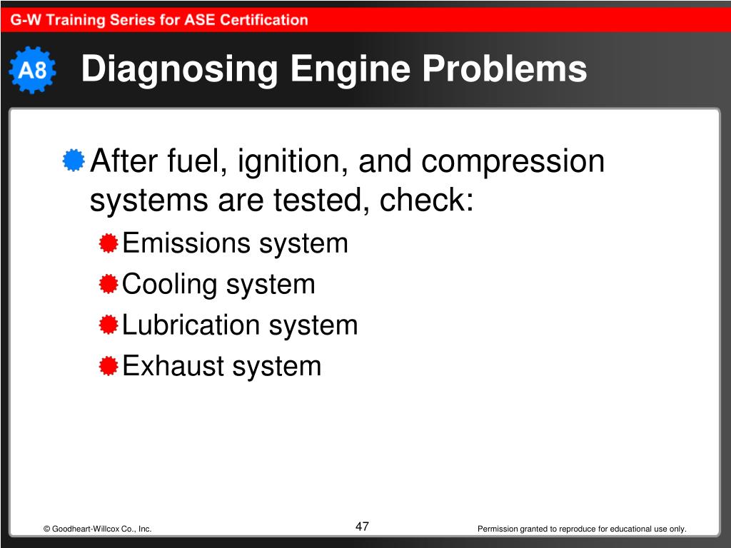
The manifold absolute pressure (MAP) sensor plays a crucial role in modern engine management systems. This small, often overlooked component measures the pressure within the intake manifold, providing vital information to the engine control unit (ECU) for precise fuel and ignition timing adjustments. A malfunctioning MAP sensor can lead to a variety of engine performance issues, including poor fuel economy, rough idling, hesitation during acceleration, and even engine stalling.
Fortunately, diagnosing a faulty MAP sensor is a relatively straightforward process that can be accomplished with the aid of a multimeter. This guide will provide a detailed explanation of how to perform this test, outlining the necessary steps, potential readings, and troubleshooting strategies.
Understanding the MAP Sensor’s Function
The MAP sensor operates on the principle of changing resistance in response to varying intake manifold pressure. It consists of a diaphragm that is sensitive to pressure changes. As pressure increases, the diaphragm flexes, altering the resistance within the sensor. The ECU interprets this resistance change to determine the intake manifold pressure, allowing it to calculate the appropriate fuel and ignition timing for optimal engine performance.
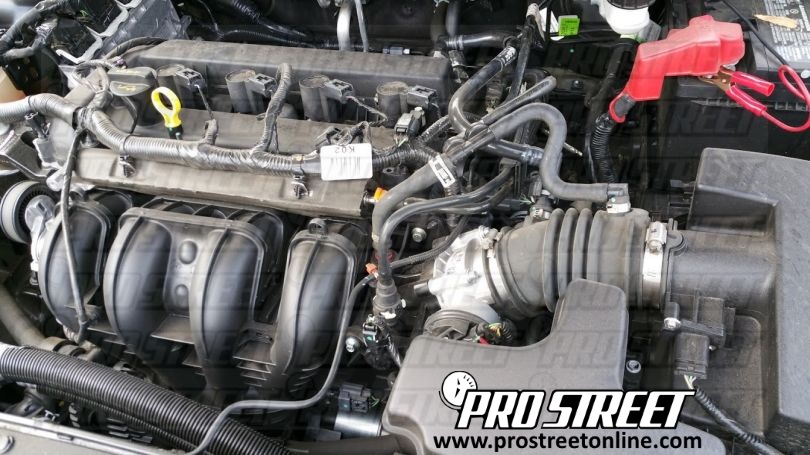
Identifying the MAP Sensor
The MAP sensor is typically located in the intake manifold, often near the throttle body or the air intake. It is usually a small, cylindrical device with a single electrical connector. Consult your vehicle’s service manual or online resources to confirm the exact location for your specific make and model.
Tools and Equipment Required
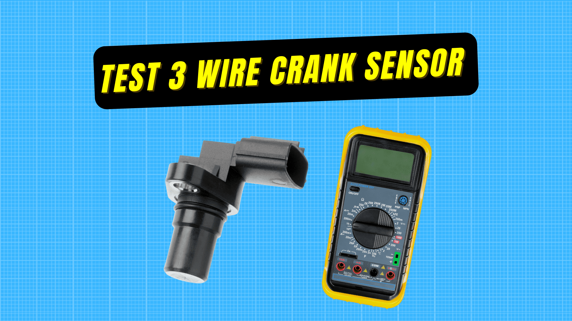
- Digital multimeter: A digital multimeter is essential for measuring voltage and resistance.
- Service manual: The service manual for your vehicle will provide detailed information about the MAP sensor, including its location, wiring diagram, and specifications.
- Safety glasses: Always wear safety glasses when working with electrical components.
- Gloves: Wearing gloves can help prevent contamination and protect your hands.
- A clean working area: Ensure a clean working area to avoid damaging the sensor or other components.
Steps to Check the MAP Sensor with a Multimeter
- Disconnect the Battery: Begin by disconnecting the negative terminal of your vehicle’s battery to prevent electrical shock and potential damage.
- Locate the MAP Sensor: Refer to your service manual to locate the MAP sensor on your vehicle.
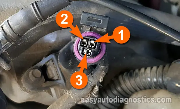
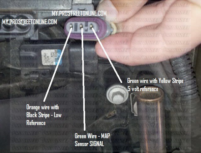
- Disconnect the Electrical Connector: Carefully disconnect the electrical connector leading to the MAP sensor.
- Inspect the Connector and Wiring: Visually inspect the connector and wiring for any signs of damage, corrosion, or loose connections. If any issues are found, address them before proceeding.
- Set the Multimeter to Resistance Mode: Set your multimeter to the resistance (Ω) mode.
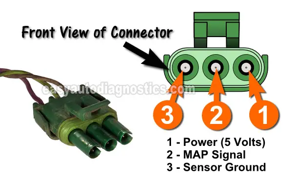
- Connect the Multimeter Leads: Connect the red lead of the multimeter to the positive terminal of the MAP sensor connector and the black lead to the negative terminal.
- Check the Resistance Reading: With the connector disconnected, the multimeter should display a resistance reading within the specified range for your vehicle. Consult your service manual for the correct resistance values.
Interpreting the Readings and Troubleshooting
- Resistance within the Specified Range: If the resistance reading falls within the specified range, the MAP sensor is likely functioning correctly. However, further testing may be necessary to confirm its performance.
- Resistance Outside the Specified Range: If the resistance reading is significantly higher or lower than the specified range, the MAP sensor may be faulty.
- No Resistance Reading: If the multimeter displays an open circuit (OL) or no reading, the MAP sensor may be completely disconnected or internally shorted.
Additional Testing Procedures
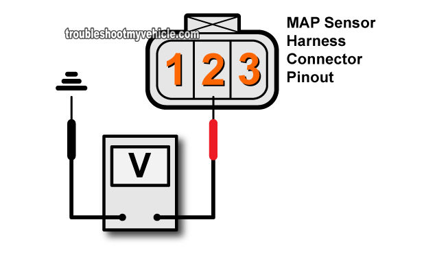
- Voltage Test: After disconnecting the MAP sensor connector, set your multimeter to DC voltage mode. Connect the red lead to the positive terminal of the connector and the black lead to the negative terminal. Apply vacuum to the MAP sensor inlet port and observe the voltage reading. The voltage should increase as vacuum increases.
- Pressure Test: If you have access to a pressure gauge, apply a known pressure to the MAP sensor inlet port and check the resistance reading. The resistance should change proportionally to the applied pressure.
Troubleshooting Common Issues
- Damaged Wiring: If the wiring is damaged, it needs to be repaired or replaced.
- Loose Connections: Ensure all connections are secure and free from corrosion.
- Faulty MAP Sensor: If the MAP sensor is faulty, it needs to be replaced.
Safety Precautions
- Disconnecting the Battery: Always disconnect the battery before working on any electrical components to prevent electrical shock.
- Working with Electrical Components: Be careful when handling electrical components, as they can be sensitive to static electricity.
- Avoid Contact with Hot Components: Allow the engine to cool down before working on any components in the engine compartment.
Conclusion
By following the steps outlined in this guide, you can effectively diagnose a faulty MAP sensor using a multimeter. This knowledge empowers you to identify and address potential engine performance issues, ensuring optimal engine operation and fuel efficiency. Remember to consult your vehicle’s service manual for specific information and specifications related to your MAP sensor. If you encounter any difficulties or are unsure about any step, it is always recommended to seek professional assistance from a qualified mechanic.
Closure
Thus, we hope this article has provided valuable insights into Diagnosing Engine Woes: A Comprehensive Guide to Checking the MAP Sensor with a Multimeter. We appreciate your attention to our article. See you in our next article!