
The Inner Workings of a MAP Sensor: A Comprehensive Guide to Construction and Function
Related Articles: The Inner Workings of a MAP Sensor: A Comprehensive Guide to Construction and Function
Introduction
In this auspicious occasion, we are delighted to delve into the intriguing topic related to The Inner Workings of a MAP Sensor: A Comprehensive Guide to Construction and Function. Let’s weave interesting information and offer fresh perspectives to the readers.
Table of Content
The Inner Workings of a MAP Sensor: A Comprehensive Guide to Construction and Function

The Manifold Absolute Pressure (MAP) sensor, a crucial component in modern internal combustion engines, plays a vital role in optimizing engine performance and fuel efficiency. This article delves into the intricate construction of MAP sensors, exploring their fundamental design principles, materials, and operational mechanisms. By understanding the internal workings of these sensors, one can gain a deeper appreciation for their significance in achieving smooth and efficient engine operation.
The Foundation of MAP Sensor Construction
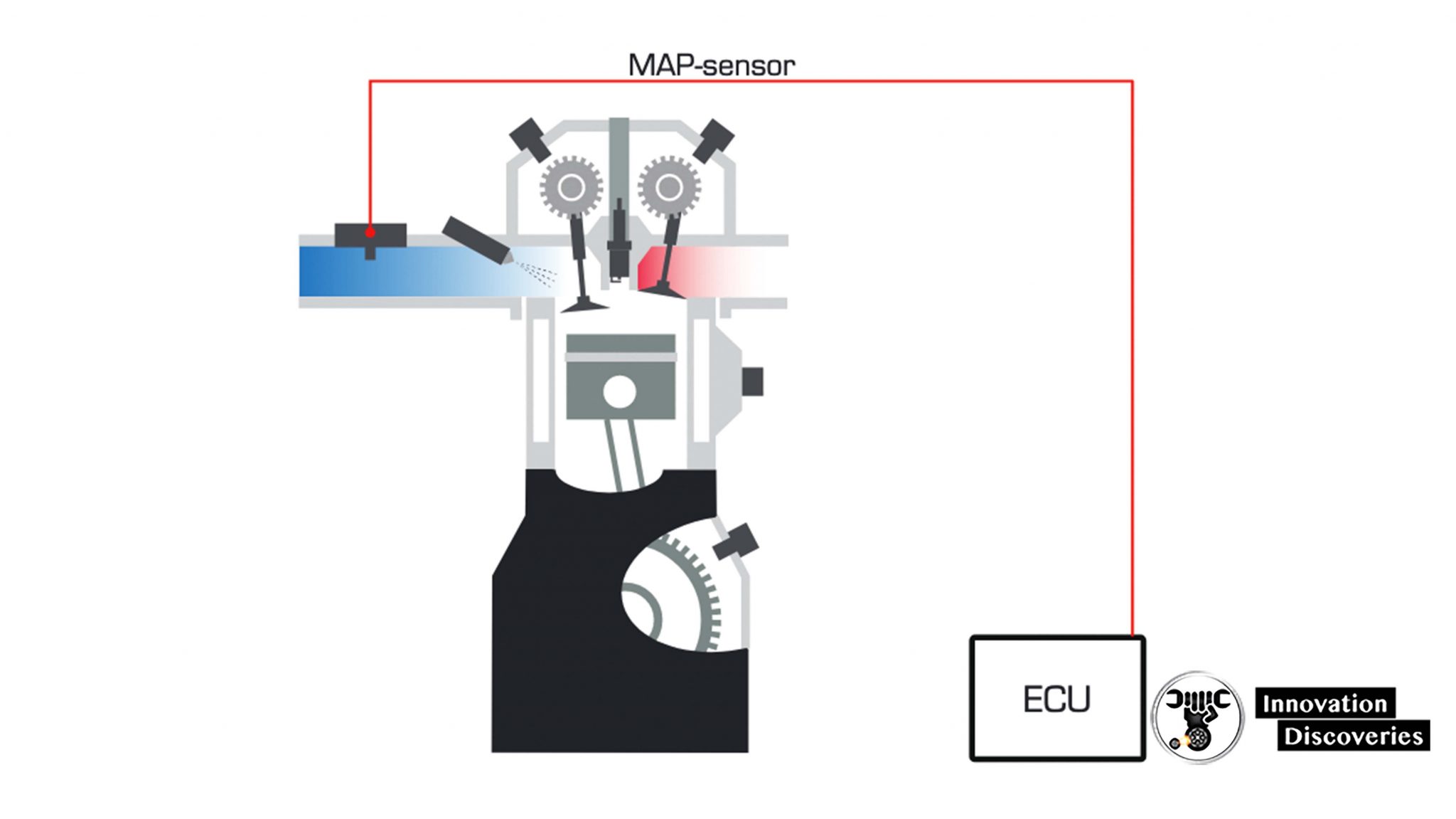
MAP sensors, essentially miniature pressure transducers, function by converting the absolute pressure within the engine intake manifold into an electrical signal. This signal, transmitted to the engine control unit (ECU), provides vital information for determining the engine load and adjusting fuel injection and ignition timing accordingly. The core of a MAP sensor’s construction lies in its ability to accurately measure pressure and translate it into a quantifiable electrical signal.
A Detailed Look at the Internal Components
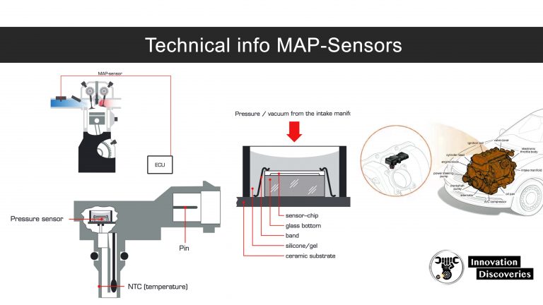
The construction of a MAP sensor typically involves the following key components:
1. Sensing Element: The heart of the MAP sensor is the sensing element, responsible for detecting the pressure variations within the intake manifold. This element is often a diaphragm, a thin, flexible membrane made from materials like silicon or metal. The diaphragm is sealed on one side, creating a sealed chamber. The other side of the diaphragm is exposed to the intake manifold pressure.
2. Strain Gauge: A strain gauge, a small, resistive element, is attached to the diaphragm. This gauge’s resistance changes proportionally to the pressure applied to the diaphragm, providing a direct measure of the intake manifold pressure.
3. Wheatstone Bridge Circuit: The strain gauge is integrated into a Wheatstone bridge circuit, a precise electrical arrangement consisting of four resistors. When the diaphragm deflects under pressure, the resistance of the strain gauge changes, altering the balance of the bridge circuit. This imbalance generates a voltage output proportional to the pressure change.
4. Signal Conditioning Circuitry: The voltage signal from the Wheatstone bridge is amplified and conditioned by a dedicated circuitry within the MAP sensor. This conditioning ensures that the signal is clean, stable, and within a specific voltage range suitable for transmission to the ECU.
5. Housing and Sealing: The entire sensor assembly is housed in a robust and weatherproof enclosure. This housing protects the internal components from environmental factors like moisture, dust, and vibration, ensuring reliable operation over the sensor’s lifespan.
Types of MAP Sensors: Exploring Variations in Construction
While the fundamental principles of MAP sensor construction remain consistent, variations exist in the specific design and materials used. These variations primarily relate to the type of sensing element employed:
1. Piezoresistive Sensors: These sensors utilize a piezoresistive material, typically silicon, as the sensing element. The material exhibits a change in electrical resistance when subjected to pressure, directly converting pressure into a measurable electrical signal.
2. Capacitive Sensors: Capacitive sensors employ a diaphragm with a variable capacitance, meaning the capacitance changes with pressure variations. The pressure change alters the distance between two conductive plates within the sensor, influencing the capacitance and generating a corresponding electrical signal.
3. Piezoelectric Sensors: Piezoelectric sensors utilize a piezoelectric material, like quartz or ceramic, which generates an electrical charge when subjected to pressure. The pressure applied to the sensor causes the material to deform, producing a voltage output proportional to the pressure.
The Importance of MAP Sensor Construction: Ensuring Accurate and Reliable Performance
The construction of a MAP sensor is critical for its accurate and reliable operation. The choice of materials, the design of the sensing element, and the precision of the electrical circuitry all contribute to the sensor’s overall performance.
1. Material Selection: The choice of materials for the diaphragm, strain gauge, and other components is crucial for ensuring durability, temperature stability, and resistance to corrosion.
2. Sensing Element Design: The sensitivity and response time of the sensing element are directly influenced by its design. A well-designed diaphragm ensures accurate pressure detection and minimal hysteresis, minimizing errors in the pressure reading.
3. Electrical Circuitry: The precision of the Wheatstone bridge circuit and the signal conditioning circuitry is essential for accurate conversion of pressure into a reliable electrical signal. Any inaccuracies in these circuits can lead to erroneous readings and affect engine performance.
4. Environmental Resistance: The housing and sealing of the sensor protect the internal components from environmental factors, ensuring long-term performance and preventing premature failure.
FAQs about MAP Sensor Construction
1. How does a MAP sensor affect engine performance?
MAP sensors provide the ECU with vital information about engine load, allowing for precise fuel injection and ignition timing adjustments. This optimization ensures smooth engine operation, efficient fuel consumption, and reduced emissions.
2. What are the common causes of MAP sensor failure?
MAP sensor failure can occur due to factors like contamination, physical damage, or electrical malfunctions. Contamination from oil or debris can affect the sensor’s sensitivity, while physical damage can lead to malfunction or complete failure.
3. How can I test a MAP sensor?
Testing a MAP sensor typically involves using a multimeter to measure the voltage output from the sensor at different pressure levels. The readings should correspond to a predetermined calibration curve for the specific sensor model.
4. Can I replace a MAP sensor myself?
Replacing a MAP sensor is generally a straightforward process, but it requires some basic mechanical knowledge and tools. Refer to your vehicle’s service manual for specific instructions and precautions.
5. What are the signs of a faulty MAP sensor?
A faulty MAP sensor can manifest as various symptoms, including rough idling, poor acceleration, engine misfires, increased fuel consumption, and difficulty starting the engine.
Tips for Maintaining MAP Sensor Performance
1. Regular Maintenance: Inspect the MAP sensor regularly for signs of contamination or damage. Clean the sensor with a suitable cleaning agent if necessary.
2. Avoid Excessive Engine Load: Avoid prolonged operation under heavy engine load, as this can stress the sensor and potentially lead to premature failure.
3. Use High-Quality Fuel: Using high-quality fuel with appropriate additives can help prevent contamination and ensure optimal sensor performance.
4. Professional Inspection: If you suspect a MAP sensor malfunction, have it inspected and replaced by a qualified mechanic.
Conclusion
The MAP sensor, with its intricate construction and sophisticated operation, plays a pivotal role in ensuring optimal engine performance and fuel efficiency. By understanding the fundamental principles behind its design and operation, one can appreciate the crucial contribution this sensor makes to the smooth and efficient operation of modern internal combustion engines. As technology continues to evolve, MAP sensors are expected to play an increasingly important role in enhancing engine performance, reducing emissions, and optimizing fuel economy.


Closure
Thus, we hope this article has provided valuable insights into The Inner Workings of a MAP Sensor: A Comprehensive Guide to Construction and Function. We appreciate your attention to our article. See you in our next article!