The Map Sensor Chart: A Comprehensive Guide to Engine Performance
Related Articles: The Map Sensor Chart: A Comprehensive Guide to Engine Performance
Introduction
In this auspicious occasion, we are delighted to delve into the intriguing topic related to The Map Sensor Chart: A Comprehensive Guide to Engine Performance. Let’s weave interesting information and offer fresh perspectives to the readers.
Table of Content
The Map Sensor Chart: A Comprehensive Guide to Engine Performance

The intricate dance of fuel and air within an internal combustion engine is a symphony of precise proportions. To ensure optimal combustion and performance, engine management systems rely on various sensors to monitor key parameters. Among these, the Manifold Absolute Pressure (MAP) sensor plays a crucial role, providing vital data to the engine control unit (ECU) about the pressure within the engine’s intake manifold. This information is critical for calculating the ideal amount of fuel to inject, ultimately influencing power output, fuel efficiency, and emissions.
A MAP sensor chart serves as a visual representation of the relationship between manifold absolute pressure and the corresponding fuel injection duration. This chart is a powerful tool for understanding engine behavior, diagnosing potential issues, and tuning for optimal performance.
Understanding the MAP Sensor Chart
The MAP sensor chart is essentially a two-dimensional graph, with manifold absolute pressure (MAP) on the x-axis and fuel injection duration on the y-axis. Each point on the chart represents a specific combination of manifold pressure and fuel injection duration, reflecting the engine’s operating conditions.
Key Components of a MAP Sensor Chart:
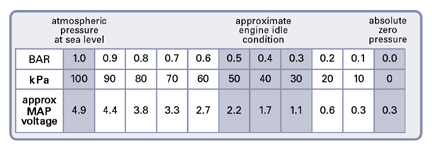
- Manifold Absolute Pressure (MAP): This axis represents the pressure within the intake manifold, typically measured in kilopascals (kPa) or inches of mercury (inHg). Higher pressure indicates a higher engine load, typically due to increased throttle opening or higher engine speeds.
- Fuel Injection Duration: This axis represents the amount of time the fuel injectors remain open, measured in milliseconds (ms). Longer injection durations correspond to a richer fuel mixture, while shorter durations indicate a leaner mixture.
- Load Lines: The chart is often divided into multiple load lines, each representing a specific engine load condition. For example, a high-load line might correspond to full throttle operation, while a low-load line might represent idle conditions.
- RPM Lines: Additional lines on the chart may represent specific engine revolutions per minute (RPM), providing further insight into the engine’s performance at different speeds.
Interpreting the MAP Sensor Chart
The MAP sensor chart provides a wealth of information about the engine’s operation, allowing for:
- Understanding Fuel Delivery: The chart clearly shows how fuel injection duration varies with manifold pressure and engine load. This information helps diagnose potential issues with fuel delivery, such as an overly rich or lean mixture.
- Identifying Engine Performance Issues: Deviations from the expected fuel injection durations can indicate problems with the MAP sensor itself, the fuel injectors, or other components within the engine management system.
- Optimizing Engine Performance: By analyzing the chart, technicians can identify areas where fuel delivery can be adjusted for improved performance, fuel economy, or emissions reduction.
Benefits of Using a MAP Sensor Chart:
- Enhanced Diagnostics: The chart provides a visual representation of engine behavior, making it easier to diagnose issues that might otherwise be difficult to pinpoint.
- Improved Tuning: By understanding the relationship between pressure and fuel injection, technicians can fine-tune engine parameters for optimal performance.
- Increased Efficiency: Accurate fuel delivery based on real-time engine conditions leads to improved fuel efficiency and reduced emissions.
- Troubleshooting Capabilities: The chart helps identify problems with the MAP sensor itself, ensuring accurate pressure readings and proper fuel delivery.
Frequently Asked Questions (FAQs) about MAP Sensor Charts
1. How are MAP sensor charts created?
MAP sensor charts are typically generated using specialized software that analyzes data from the engine control unit (ECU). This data includes real-time readings from the MAP sensor, fuel injectors, and other sensors.
2. What does a flat line on the MAP sensor chart indicate?
A flat line on the MAP sensor chart could indicate a problem with the MAP sensor itself, such as a faulty sensor or a clogged vacuum line. It could also indicate a problem with the ECU, preventing it from receiving accurate pressure readings.
3. Can a MAP sensor chart be used for all engines?
While the basic principles of the MAP sensor chart apply to most internal combustion engines, specific charts are tailored to individual engine models and configurations. Factors such as engine size, fuel type, and air intake system can influence the chart’s appearance.
4. How often should a MAP sensor be checked?
It is generally recommended to have the MAP sensor checked during routine engine maintenance, typically every 30,000-60,000 miles. However, if you notice any signs of engine performance issues, such as poor fuel economy, hesitation, or rough idling, it’s advisable to have the sensor checked sooner.
5. Can I adjust the MAP sensor chart myself?
Adjusting the MAP sensor chart requires specialized knowledge and tools. It is generally recommended to leave this task to qualified technicians who have experience with engine tuning and diagnostics.
Tips for Using a MAP Sensor Chart Effectively
- Understand Engine Specifics: Before interpreting a MAP sensor chart, familiarize yourself with the specific engine model and its operating parameters.
- Compare to Baseline Data: Use a baseline chart from a known good engine to compare with the current engine’s data for easier identification of deviations.
- Consider Environmental Factors: Ambient temperature, altitude, and air density can influence engine performance and affect the MAP sensor readings.
- Seek Professional Assistance: If you are unsure about interpreting the chart or making adjustments, consult a qualified technician for professional guidance.
Conclusion
The MAP sensor chart is a powerful diagnostic and tuning tool for understanding and optimizing engine performance. By providing a clear visualization of the relationship between manifold pressure and fuel injection duration, it allows technicians to identify potential issues, fine-tune engine parameters, and ensure optimal fuel delivery. Understanding and utilizing this chart effectively can significantly improve engine efficiency, reduce emissions, and enhance overall performance.

Closure
Thus, we hope this article has provided valuable insights into The Map Sensor Chart: A Comprehensive Guide to Engine Performance. We hope you find this article informative and beneficial. See you in our next article!
