
Understanding Sensor Data: Mapping Analog Values to Digital Outputs
Related Articles: Understanding Sensor Data: Mapping Analog Values to Digital Outputs
Introduction
With great pleasure, we will explore the intriguing topic related to Understanding Sensor Data: Mapping Analog Values to Digital Outputs. Let’s weave interesting information and offer fresh perspectives to the readers.
Table of Content
Understanding Sensor Data: Mapping Analog Values to Digital Outputs
In the realm of embedded systems and sensor technology, the ability to effectively translate analog sensor readings into digital values is paramount. This process, known as analog-to-digital conversion (ADC), plays a crucial role in bridging the gap between the physical world and the digital domain. One common technique employed in this conversion is mapping sensor values using a defined range, often expressed as "outputvalue map sensorvalue 0 1023 0 255." This article aims to demystify this mapping process, highlighting its significance and application in various scenarios.
Analog Sensors and Digital Systems
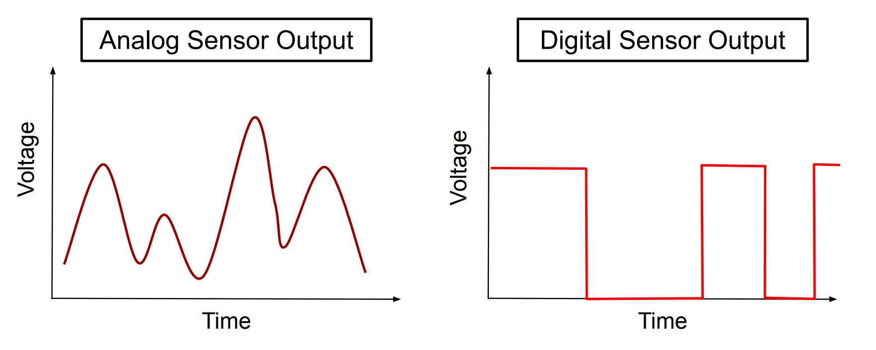
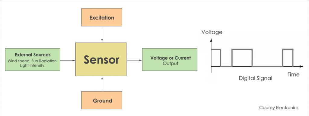
Sensors, the eyes and ears of our machines, measure physical quantities like temperature, pressure, light intensity, or position. These measurements are often analog, meaning they vary continuously over a range of values. However, digital systems, the brains of our machines, operate on discrete values represented as binary digits (0s and 1s). Therefore, a bridge is needed to translate analog sensor readings into digital signals that can be processed and interpreted by digital systems.
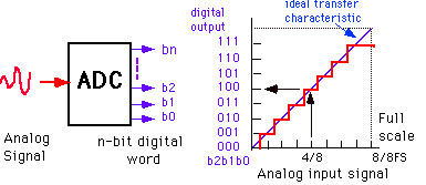
The Role of Analog-to-Digital Conversion (ADC)
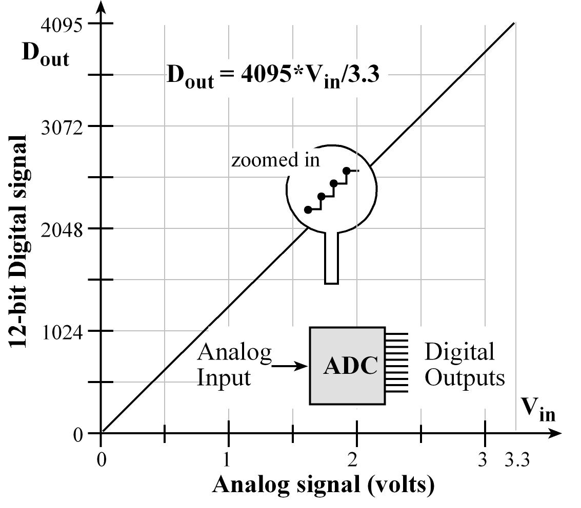
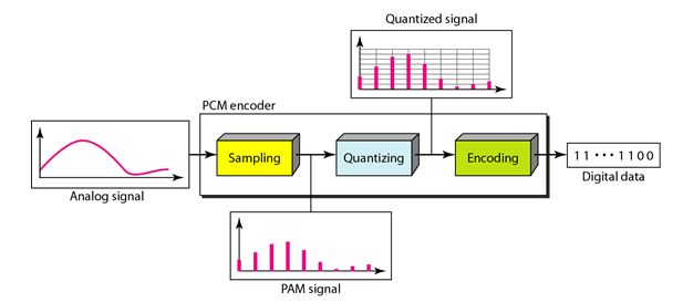
This bridge is provided by Analog-to-Digital Converters (ADCs). ADCs convert continuous analog signals into discrete digital values. The process involves sampling the analog signal at regular intervals and assigning a corresponding digital value based on the signal’s magnitude at that moment.
Mapping Sensor Values: A Practical Example
Consider a temperature sensor that outputs a voltage proportional to the temperature. The sensor’s output voltage might range from 0 to 5 volts. However, a microcontroller, the processing unit, might only be able to handle values between 0 and 255. This is where the mapping comes into play.
The "outputvalue map sensorvalue 0 1023 0 255" notation represents a linear mapping scheme. It indicates that the sensor’s output value, ranging from 0 to 1023, will be mapped to a corresponding output value ranging from 0 to 255. This mapping ensures that the microcontroller receives a value within its acceptable range, even though the sensor’s output is outside that range.
The Importance of Mapping
This mapping process is crucial for several reasons:
- Data Scaling: It allows for scaling the sensor’s output to a range suitable for the digital system.
- Normalization: It standardizes the data, making it easier to compare readings from different sensors or systems.
- Resolution: By mapping the sensor’s output to a smaller range, it can increase the resolution of the digital representation, providing a more precise measurement.
- Efficiency: Mapping can optimize data processing by simplifying calculations and reducing computational overhead.
Understanding the Mapping Equation
The mapping equation for "outputvalue map sensorvalue 0 1023 0 255" can be expressed as:
OutputValue = (SensorValue * OutputRange) / SensorRangeWhere:
- OutputValue: The digital value output by the microcontroller.
- SensorValue: The analog value read from the sensor.
- OutputRange: The desired range for the digital output (0 to 255 in this case).
- SensorRange: The full range of the sensor’s output (0 to 1023 in this case).
Example Calculation:
If the sensor reads a value of 512, the corresponding output value would be:
OutputValue = (512 * 255) / 1023 = 127.5Since the microcontroller can only handle integer values, the output value would be rounded to 128.
Applications of Sensor Value Mapping
The mapping of sensor values finds widespread applications in various fields, including:
- Industrial Automation: Controlling motors, actuators, and other industrial equipment based on sensor readings.
- Robotics: Enabling robots to interact with their environment by interpreting sensor data.
- Environmental Monitoring: Monitoring air quality, water quality, and other environmental parameters.
- Medical Devices: Measuring vital signs like heart rate, blood pressure, and oxygen levels.
- Consumer Electronics: Controlling devices like smartphones, smart home appliances, and wearable fitness trackers.
FAQs
Q1: Why is the sensor range often 0 to 1023?
A1: The range 0 to 1023 is commonly associated with 10-bit Analog-to-Digital Converters (ADCs). A 10-bit ADC can represent 2^10 = 1024 distinct values, ranging from 0 to 1023.
Q2: How do I choose the output range?
A2: The output range should be chosen based on the requirements of the microcontroller or the system that will process the data. It should be within the acceptable range of the receiving system and provide sufficient resolution for the application.
Q3: What happens if the sensor value exceeds the sensor range?
A3: If the sensor value exceeds the defined range, the mapping process will either clip the value to the maximum limit or produce an invalid output. It’s crucial to ensure the sensor’s output stays within the specified range to avoid data corruption.
Q4: Can I use a non-linear mapping scheme?
A4: Yes, non-linear mapping schemes can be used for situations where the sensor’s output is not linearly proportional to the measured quantity. For example, a logarithmic mapping might be used for sensors with an exponential response.
Tips for Effective Sensor Value Mapping
- Understand the sensor’s specifications: Know the sensor’s output range, resolution, and any non-linearity in its response.
- Choose the appropriate output range: Select a range that matches the capabilities of the processing system.
- Implement error handling: Include measures to handle cases where the sensor value exceeds the range or produces invalid data.
- Test and calibrate: Thoroughly test the mapping process and calibrate the sensor to ensure accurate data conversion.
Conclusion
Mapping sensor values is a fundamental step in integrating analog sensors with digital systems. By converting analog readings into digital values within a defined range, the "outputvalue map sensorvalue 0 1023 0 255" scheme enables seamless communication between the physical world and the digital domain. This process is essential for a wide range of applications, from industrial automation to consumer electronics, enabling machines to perceive and react to their surroundings in a meaningful way. Understanding the principles of sensor value mapping empowers engineers and developers to effectively utilize sensor data in their projects, unlocking the potential of these ubiquitous devices for innovation and advancement.


Closure
Thus, we hope this article has provided valuable insights into Understanding Sensor Data: Mapping Analog Values to Digital Outputs. We hope you find this article informative and beneficial. See you in our next article!