
Understanding the Holley Terminator X MAP Sensor Wiring Diagram: A Guide to Precise Engine Control
Related Articles: Understanding the Holley Terminator X MAP Sensor Wiring Diagram: A Guide to Precise Engine Control
Introduction
With enthusiasm, let’s navigate through the intriguing topic related to Understanding the Holley Terminator X MAP Sensor Wiring Diagram: A Guide to Precise Engine Control. Let’s weave interesting information and offer fresh perspectives to the readers.
Table of Content
Understanding the Holley Terminator X MAP Sensor Wiring Diagram: A Guide to Precise Engine Control

The Holley Terminator X is a renowned engine management system known for its versatility and performance capabilities. A critical component within this system is the Manifold Absolute Pressure (MAP) sensor, which plays a crucial role in determining engine load and providing accurate fuel and ignition adjustments. Understanding the wiring diagram for this sensor is essential for proper installation, troubleshooting, and optimizing the performance of your engine.
The Role of the MAP Sensor in Engine Management
The MAP sensor is a crucial element in the engine’s feedback loop. It measures the pressure within the intake manifold, providing the engine control unit (ECU) with real-time information about the engine’s load. This data is then used to determine the appropriate amount of fuel and ignition timing required for optimal combustion.
Deciphering the Holley Terminator X MAP Sensor Wiring Diagram
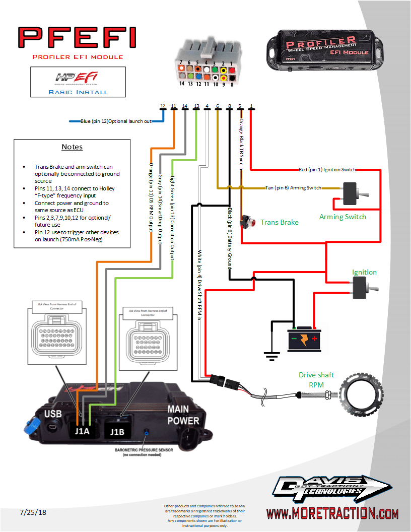
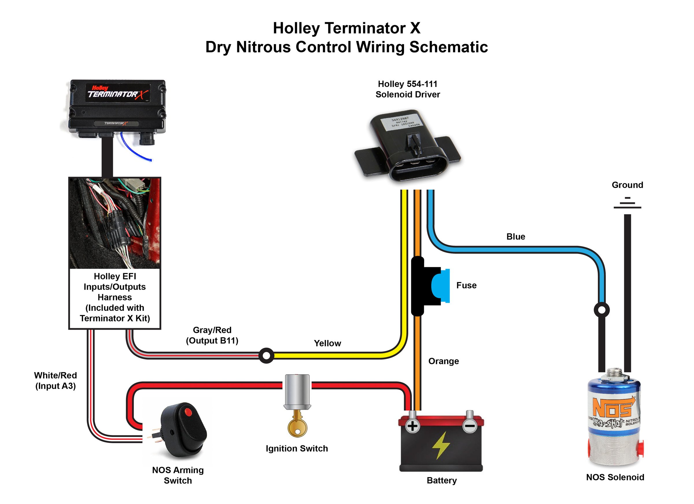
The Holley Terminator X MAP sensor wiring diagram is a visual representation of the connections between the sensor, the ECU, and other components. It typically includes:
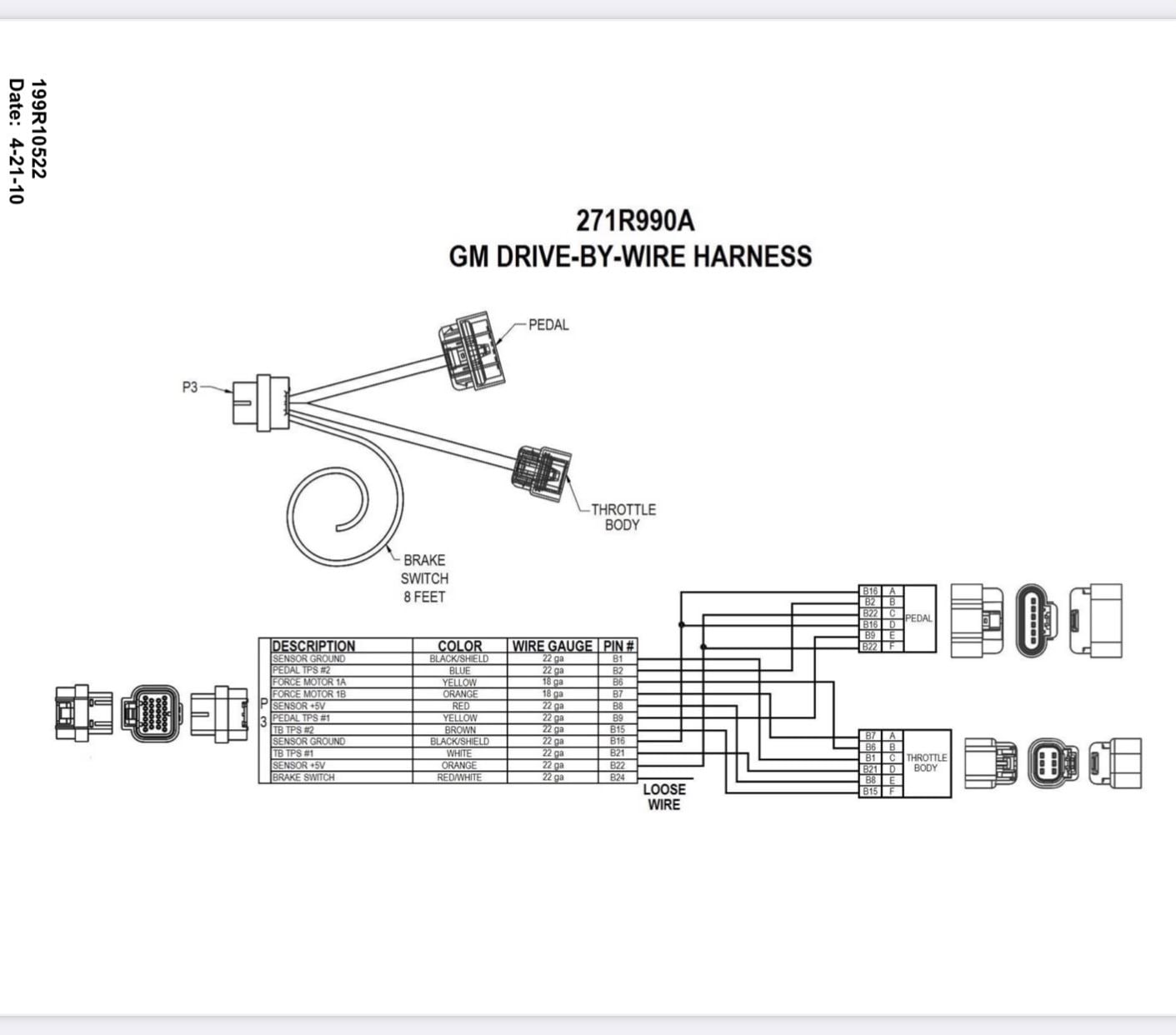
- Sensor Connections: The diagram will clearly identify the sensor’s terminals, often labeled with letters or numbers.
- ECU Connections: The corresponding connections on the ECU will be indicated, ensuring proper wiring.
- Voltage and Ground: The diagram will show the power supply (usually a 5-volt reference) and ground connections for the sensor.
- Signal Wire: The signal wire carries the pressure readings from the sensor to the ECU.
Key Points to Note:
- Sensor Type: The Holley Terminator X system utilizes a specific type of MAP sensor. It is crucial to ensure that the correct sensor is used and that the wiring diagram corresponds to the chosen sensor.
- Signal Range: The sensor’s output signal range varies depending on the model. The wiring diagram will specify the appropriate voltage range for the signal wire.
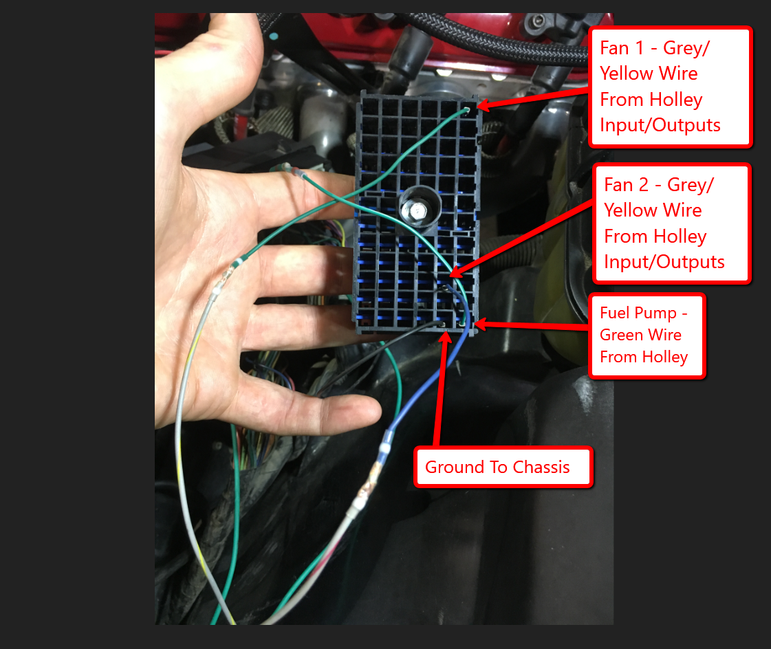
- Color Coding: Holley uses color-coded wires for identification. The diagram will clearly indicate the color of each wire, making it easier to match them during installation.
Benefits of Understanding the Wiring Diagram:
- Accurate Installation: The diagram provides a clear guide for connecting the sensor to the ECU, ensuring proper function.
- Troubleshooting Issues: If the engine experiences performance problems, the wiring diagram helps identify potential issues related to the MAP sensor.
- Optimizing Performance: By understanding the sensor’s function and its relationship with the ECU, tuners can fine-tune the engine’s settings for optimal performance.
FAQs on Holley Terminator X MAP Sensor Wiring Diagram
Q1: What happens if the MAP sensor is not connected or is faulty?
A: A disconnected or faulty MAP sensor will prevent the ECU from receiving accurate engine load information. This can lead to poor fuel economy, rough idle, stalling, and even engine damage.
Q2: How can I test the MAP sensor for proper function?
A: A multimeter can be used to test the sensor’s resistance and voltage output. Refer to the Holley documentation or consult a qualified technician for specific testing procedures.
Q3: Can I use a different type of MAP sensor with the Holley Terminator X system?
A: It is not recommended to use a different type of MAP sensor without proper calibration and configuration. The ECU is designed to work with a specific sensor, and using a different one may result in inaccurate readings and performance issues.
Q4: How do I adjust the MAP sensor settings in the Holley Terminator X software?
A: The Holley Terminator X software provides options for configuring the MAP sensor settings. These settings include the sensor type, signal range, and calibration values. Refer to the Holley documentation for detailed instructions.
Tips for Working with the Holley Terminator X MAP Sensor Wiring Diagram
- Use a Reliable Source: Obtain the wiring diagram directly from Holley’s website or from a trusted source.
- Double-Check Connections: Carefully verify each connection before starting the engine.
- Utilize a Wiring Diagram Tool: Consider using a wiring diagram tool to help visualize and troubleshoot connections.
- Consult a Professional: If you are not comfortable working with electrical systems, consult a qualified technician for assistance.
Conclusion
The Holley Terminator X MAP sensor wiring diagram is a vital tool for anyone working with this engine management system. By understanding the diagram and the role of the MAP sensor in engine control, users can ensure proper installation, troubleshoot potential issues, and optimize engine performance. Investing time in understanding this diagram can significantly enhance your ability to manage and fine-tune your engine for optimal power and efficiency.


Closure
Thus, we hope this article has provided valuable insights into Understanding the Holley Terminator X MAP Sensor Wiring Diagram: A Guide to Precise Engine Control. We thank you for taking the time to read this article. See you in our next article!