
Understanding the Language of Your Engine: Decoding the MAP Sensor Voltage Chart
Related Articles: Understanding the Language of Your Engine: Decoding the MAP Sensor Voltage Chart
Introduction
With enthusiasm, let’s navigate through the intriguing topic related to Understanding the Language of Your Engine: Decoding the MAP Sensor Voltage Chart. Let’s weave interesting information and offer fresh perspectives to the readers.
Table of Content
- 1 Related Articles: Understanding the Language of Your Engine: Decoding the MAP Sensor Voltage Chart
- 2 Introduction
- 3 Understanding the Language of Your Engine: Decoding the MAP Sensor Voltage Chart
- 3.1 What is a MAP Sensor Voltage Chart?
- 3.2 Key Factors Influencing MAP Sensor Voltage:
- 3.3 Common MAP Sensor Problems and their Impact on Voltage Output:
- 3.4 FAQs about MAP Sensor Voltage Charts:
- 3.5 Tips for Using a MAP Sensor Voltage Chart:
- 3.6 Conclusion:
- 4 Closure
Understanding the Language of Your Engine: Decoding the MAP Sensor Voltage Chart
The intricate dance of modern engines relies on a symphony of sensors, each playing a critical role in ensuring optimal performance. Among these vital components, the Manifold Absolute Pressure (MAP) sensor stands out as a crucial voice, relaying critical information about the engine’s intake manifold pressure to the engine control unit (ECU). This data, communicated in the form of voltage signals, provides the ECU with the necessary information to adjust fuel delivery and ignition timing, ultimately optimizing combustion and fuel efficiency.
Understanding the relationship between manifold pressure and the corresponding MAP sensor voltage output is paramount for diagnosing engine issues and ensuring proper operation. This is where the MAP sensor voltage chart comes into play, acting as a vital tool for technicians and enthusiasts alike.
What is a MAP Sensor Voltage Chart?
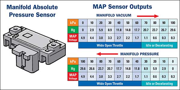
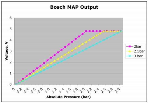
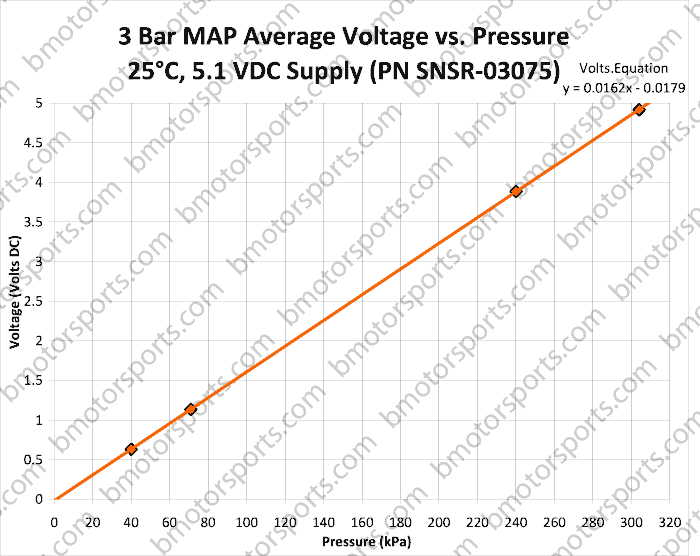
A MAP sensor voltage chart is a visual representation of the relationship between manifold absolute pressure (in kilopascals or inches of mercury) and the corresponding voltage output from the MAP sensor (in volts). This chart serves as a crucial reference point for interpreting the sensor’s readings and identifying potential problems.
Understanding the Chart:
The chart typically depicts manifold pressure on the horizontal axis and the corresponding MAP sensor voltage on the vertical axis. The relationship between these two variables is usually linear, meaning that as manifold pressure increases, the voltage output from the MAP sensor also increases proportionally.
Interpreting the Data:
By comparing the actual voltage output from the MAP sensor with the expected values on the chart, technicians can determine if the sensor is functioning correctly. Deviations from the expected values can indicate a faulty sensor, a vacuum leak, or other issues affecting the engine’s intake manifold pressure.
Benefits of Using a MAP Sensor Voltage Chart:
- Accurate Diagnosis: The chart provides a clear visual representation of the expected sensor output, allowing for quick and accurate diagnosis of potential problems.
- Troubleshooting Efficiency: By comparing actual sensor readings with the chart, technicians can pinpoint the source of the issue, saving time and resources during troubleshooting.
- Performance Optimization: The chart allows for precise tuning of the engine control unit, ensuring optimal fuel delivery and ignition timing for peak performance.
- Understanding Engine Behavior: The chart provides valuable insights into the engine’s operating conditions, allowing for better understanding of its performance characteristics.
Key Factors Influencing MAP Sensor Voltage:
Several factors can influence the voltage output of a MAP sensor, including:
- Engine Load: As engine load increases, manifold pressure also rises, leading to a higher MAP sensor voltage.
- Engine RPM: Higher engine RPMs typically result in higher manifold pressure, leading to a higher MAP sensor voltage.
- Intake Manifold Temperature: Higher intake manifold temperatures can affect the density of the air in the manifold, influencing manifold pressure and the MAP sensor voltage.
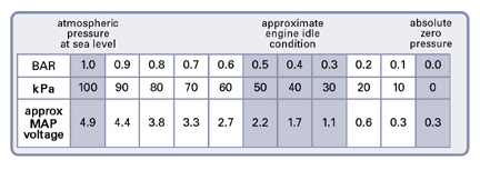
- Altitude: At higher altitudes, atmospheric pressure decreases, leading to lower manifold pressure and a lower MAP sensor voltage.
Common MAP Sensor Problems and their Impact on Voltage Output:
- Faulty Sensor: A malfunctioning MAP sensor can produce inaccurate voltage readings, leading to engine performance issues.
- Vacuum Leak: A vacuum leak in the intake manifold can cause lower than expected manifold pressure, resulting in a lower MAP sensor voltage.
- Clogged Sensor Ports: Obstructions in the sensor ports can interfere with the accurate measurement of manifold pressure, leading to inaccurate voltage readings.
- Wiring Issues: Damaged or faulty wiring can disrupt the signal flow from the MAP sensor to the ECU, causing inaccurate voltage readings.
FAQs about MAP Sensor Voltage Charts:
1. Where can I find a MAP Sensor voltage chart for my specific vehicle?
MAP sensor voltage charts are often available in repair manuals, online automotive forums, and technical databases specific to your vehicle’s make and model.
2. How do I use a MAP Sensor voltage chart to diagnose a problem?
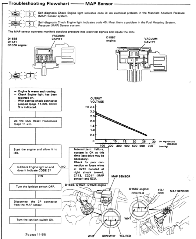
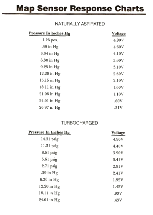
Connect a scan tool to your vehicle and record the MAP sensor voltage reading under various engine conditions. Compare these readings to the expected values on the chart. Significant deviations from the expected values can indicate a problem.
3. What are the typical voltage ranges for a MAP sensor?
MAP sensor voltage ranges vary depending on the vehicle model and sensor type. However, common ranges typically fall between 0.5 volts and 5 volts.
4. Can I use a multimeter to test the MAP sensor voltage?
Yes, you can use a multimeter to test the MAP sensor voltage. Consult your vehicle’s repair manual for specific instructions on accessing the sensor and measuring its voltage output.
5. Can I replace the MAP sensor myself?
Replacing a MAP sensor is generally a straightforward task, but it requires basic mechanical knowledge and tools. Consult your vehicle’s repair manual for specific instructions and safety precautions.
Tips for Using a MAP Sensor Voltage Chart:
- Consult Your Vehicle’s Repair Manual: Always refer to your vehicle’s repair manual for specific information about your MAP sensor, including voltage ranges and diagnostic procedures.
- Use a Reliable Scan Tool: Invest in a high-quality scan tool capable of accurately reading and displaying MAP sensor voltage readings.
- Understand the Chart’s Context: Remember that the chart represents a general relationship between manifold pressure and voltage. Actual readings may vary slightly depending on engine conditions and sensor calibration.
- Consider Environmental Factors: Account for environmental factors such as altitude and temperature, which can affect manifold pressure and sensor readings.
Conclusion:
The MAP sensor voltage chart serves as a powerful tool for diagnosing engine problems and optimizing performance. By understanding the relationship between manifold pressure and sensor voltage, technicians and enthusiasts can gain valuable insights into the engine’s operating conditions and ensure optimal performance.
While the chart provides a valuable reference point, it’s essential to consider the broader context of engine operation and consult with qualified professionals when troubleshooting complex issues. By mastering the language of the MAP sensor voltage chart, you can unlock a deeper understanding of your engine’s intricate workings and ensure its smooth and efficient operation.


Closure
Thus, we hope this article has provided valuable insights into Understanding the Language of Your Engine: Decoding the MAP Sensor Voltage Chart. We thank you for taking the time to read this article. See you in our next article!