Unraveling the Secrets of the Manifold Absolute Pressure Sensor: A Comprehensive Guide to MAP Sensor Graphs
Related Articles: Unraveling the Secrets of the Manifold Absolute Pressure Sensor: A Comprehensive Guide to MAP Sensor Graphs
Introduction
With enthusiasm, let’s navigate through the intriguing topic related to Unraveling the Secrets of the Manifold Absolute Pressure Sensor: A Comprehensive Guide to MAP Sensor Graphs. Let’s weave interesting information and offer fresh perspectives to the readers.
Table of Content
Unraveling the Secrets of the Manifold Absolute Pressure Sensor: A Comprehensive Guide to MAP Sensor Graphs

The manifold absolute pressure sensor (MAP sensor) plays a crucial role in modern internal combustion engines, providing vital information about the air pressure within the intake manifold. This data is critical for the engine control unit (ECU) to accurately calculate fuel injection timing and duration, ultimately optimizing engine performance and fuel efficiency. Understanding the nuances of MAP sensor graphs, which depict the relationship between manifold pressure and engine operating conditions, is essential for diagnosing engine problems and ensuring optimal engine operation.
The Anatomy of a MAP Sensor Graph
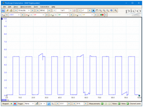
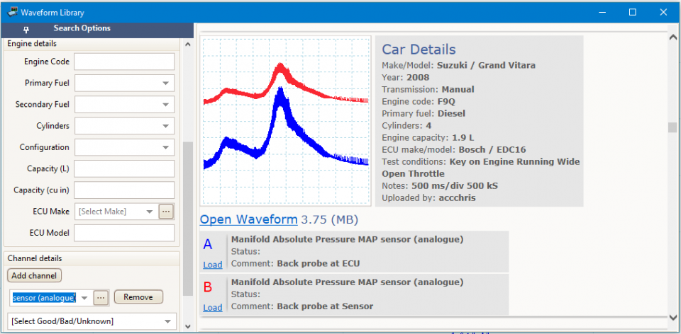
A typical MAP sensor graph is a two-dimensional representation, with manifold absolute pressure (MAP) on the vertical axis and engine load or speed on the horizontal axis. The graph showcases the manifold pressure across a range of engine operating conditions, providing a visual representation of how the engine breathes.
Key Components of a MAP Sensor Graph:
- Manifold Absolute Pressure (MAP): Measured in kilopascals (kPa) or inches of mercury (inHg), this value represents the absolute pressure within the intake manifold. It reflects the amount of air being drawn into the engine during each intake stroke.
- Engine Load: This parameter reflects the demand placed upon the engine, often represented by throttle position or engine vacuum. Higher engine load corresponds to a greater demand for air and consequently, higher manifold pressure.
- Engine Speed: Measured in revolutions per minute (RPM), this parameter reflects the rate at which the engine crankshaft is rotating. Engine speed influences the amount of air that can be drawn into the engine during each intake cycle.
Understanding the Dynamics of MAP Sensor Graphs:
The shape of the MAP sensor graph reveals valuable insights into engine performance and can be used to diagnose potential issues.
- Linearity: An ideal MAP sensor graph exhibits a linear relationship between manifold pressure and engine load, indicating a consistent response to changes in engine demand.
- Slope: The slope of the graph reveals the responsiveness of the engine to changes in load. A steeper slope suggests a more responsive engine, while a shallower slope indicates a less responsive engine.
- Plateau: A plateau in the graph indicates a point where the manifold pressure reaches a maximum value, irrespective of further increases in engine load. This plateau can be indicative of limitations in the engine’s ability to draw in more air, such as a restriction in the intake system.
- Deviations: Any deviations from the expected linear relationship or plateau behavior can indicate potential issues with the MAP sensor, intake system, or other engine components.
Interpreting MAP Sensor Graph Data:
Analyzing MAP sensor graphs requires a comprehensive understanding of the engine operating conditions and their impact on manifold pressure.
- Idle: At idle, the engine operates at low speed and low load, resulting in low manifold pressure. The MAP sensor graph typically shows a low value for MAP at idle.
- Acceleration: During acceleration, the throttle opens, increasing engine load and manifold pressure. The MAP sensor graph reflects this increase in pressure, revealing the engine’s response to the demand for more power.
- Cruising: At steady-state cruising conditions, the engine operates at a moderate speed and load, resulting in a stable manifold pressure. The MAP sensor graph showcases a relatively constant MAP value during cruising.
- Deceleration: When the engine decelerates, the throttle closes, reducing engine load and manifold pressure. The MAP sensor graph reflects this decrease in pressure, indicating the engine’s response to reduced demand.
Applications of MAP Sensor Graphs:
MAP sensor graphs are invaluable tools for:
- Engine Diagnosis: Deviations from the expected MAP sensor graph patterns can indicate potential issues such as leaks in the intake system, faulty MAP sensor, or problems with the engine control unit (ECU).
- Performance Tuning: By analyzing MAP sensor graphs, engine tuners can identify areas for optimization, such as adjusting fuel injection timing and duration for improved performance and fuel efficiency.
- Research and Development: MAP sensor graphs are used in research and development to evaluate engine performance under various operating conditions and optimize engine designs.
FAQs about MAP Sensor Graphs:
Q1: What are the common causes of deviations in MAP sensor graphs?
A: Deviations from expected MAP sensor graph patterns can be caused by a variety of factors, including:
- Faulty MAP Sensor: A malfunctioning MAP sensor can provide inaccurate pressure readings, leading to deviations in the graph.
- Leaks in the Intake System: Leaks in the intake manifold, vacuum lines, or other components can reduce manifold pressure, resulting in deviations from the expected graph.
- Blocked Intake System: Obstructions in the intake system, such as a clogged air filter, can restrict airflow and reduce manifold pressure, leading to deviations in the graph.
- Engine Control Unit (ECU) Issues: Problems with the ECU, such as faulty programming or sensor input errors, can lead to inaccurate calculations of manifold pressure and deviations in the graph.
Q2: How can I diagnose a faulty MAP sensor using a MAP sensor graph?
A: A faulty MAP sensor can manifest in various ways on a MAP sensor graph:
- Inconsistent Readings: The MAP sensor may provide inconsistent readings across similar engine operating conditions, leading to erratic fluctuations in the graph.
- Lack of Response: The MAP sensor may fail to respond to changes in engine load or speed, resulting in a flat or unresponsive graph.
- Offset Readings: The MAP sensor may consistently provide readings that are significantly higher or lower than expected, leading to a graph that is shifted upwards or downwards.
Q3: How can I use MAP sensor graphs to improve engine performance?
A: By analyzing MAP sensor graphs, engine tuners can identify areas for optimization, such as:
- Adjusting Fuel Injection Timing: By analyzing the relationship between manifold pressure and engine speed, tuners can adjust fuel injection timing to ensure optimal combustion and power output.
- Optimizing Fuel Injection Duration: By analyzing the relationship between manifold pressure and engine load, tuners can adjust fuel injection duration to ensure efficient fuel consumption and reduce emissions.
- Identifying Intake System Restrictions: By analyzing the plateau in the MAP sensor graph, tuners can identify potential restrictions in the intake system and address them to improve airflow and engine performance.
Tips for Understanding and Utilizing MAP Sensor Graphs:
- Familiarize yourself with the engine operating conditions: Understanding how engine speed, load, and other parameters influence manifold pressure is crucial for interpreting MAP sensor graphs.
- Compare graphs to known good data: Comparing the MAP sensor graph to known good data for the same engine model can help identify deviations and potential issues.
- Use specialized software: Dedicated software tools designed for analyzing MAP sensor graphs can provide valuable insights and facilitate diagnosis and tuning.
- Consult with a qualified technician: If you are unsure about interpreting MAP sensor graphs or diagnosing engine problems, consult with a qualified automotive technician for professional assistance.
Conclusion:
MAP sensor graphs provide a powerful tool for understanding and optimizing engine performance. By analyzing the relationship between manifold pressure and engine operating conditions, technicians and tuners can identify potential issues, diagnose problems, and improve engine performance and fuel efficiency. With a comprehensive understanding of MAP sensor graphs and their interpretation, it is possible to ensure optimal engine operation and maximize the potential of modern internal combustion engines.


Closure
Thus, we hope this article has provided valuable insights into Unraveling the Secrets of the Manifold Absolute Pressure Sensor: A Comprehensive Guide to MAP Sensor Graphs. We appreciate your attention to our article. See you in our next article!
